Random Quote Board
Gnu Radio and Sample Rate
Perhaps one of the most misunderstood aspects of Gnu Radio, and SDR in general, is the concept of sample rate. Let's go through it a little bit at a time.
SDR and Digitizing
A software defined radio (SDR) has two, basic purposes. These are:
- Amplify, filter and frequency shift RF signals to an intermediate frequency (IF). The first part of all SDRs is the RF front end. When you connect an antenna to your SDR, regardless of the SDR you have, the signals will pass through this section. There will most likely be an amplifier and some filtering. There may or may not be a frequency conversion circuit depending on the frequency range of the SDR. SDRs that operate in the HF range (3 - 30 MHz) or less may go directly from an amplifier and/or filter direct to a digitizer. No need for frequency conversion. Those systems simply digitize the whole spectrum, then perform any needed frequency conversion in software. If the SDR does have a frequency conversion circuit, it most likely is a superheterodyne system. This simply means that it converts tuned frequency to a fixed intermediate frequency (IF). This is an age-old technique that allows for any follow-on circuits to operate on just one frequency. This makes them much simpler, which in turn makes them cheaper and more reliable.
- Digitize the RF signals. All RF signals are analog. SDRs means "software". Software means computers. Computers, at least the ones we tend to use, do not work on analog signals. We need digital. Therefore, there will be a circuit to convert the analog signal to a digital signal. That's the digitizer or analog-to-digital converter (ADC). Any follow-on circuitry will do nothing more than prepare the samples for transfer over a USB or Ethernet connection.

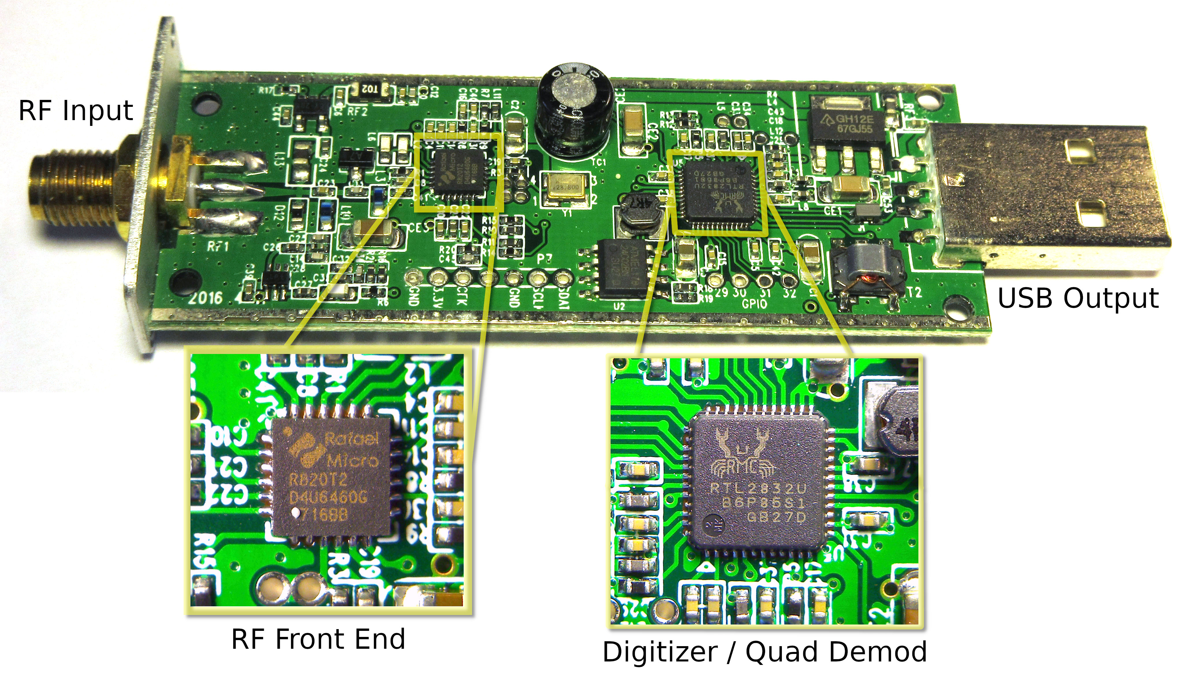
There's one other function that SDRs almost always do but they do not have to do, and that is to turn the input signals, which are real, and turn them into complex signals. The two SDRs shown above both output complex digital samples. The Signal Hound BB60C, however, outputs real samples, then the computer, using software, turns them into complex samples.
Real vs Complex Samples
I still don't have a good write-up to explain the difference between real vs complex samples. Someday, maybe. There are plenty of other people on these here interwebz who have taken a stab at explaining the difference between real vs complex sampling. Check those out. In the mean time, let me boil this down to two key concepts that I always bear in mind when processing digital signals.
- Required sample rate. There's a difference in the required sample rate between these two signal types. The sample rate for real signals must be at least twice the bandwidth of the sampled signal. The sample rate for complex signals must be at least equal to the bandwidth of the sampled signal. Let me add this. No, having a sample rate equal to the bandwidth of the sampled signal does not mean we're violating Nyquist. Because of the combination of real and imaginary components, we can use the full sample rate spectrum, rather than being limited to 1/2 of it. The downside is that, even though complex samples only require half the sample rate of real samples, they require twice as many bits. A complex sample consists of two parts, a real part and an imaginary part. Hence, it requires twice the memory to store a complex sample as a real one. The point is that the overall bit rate will be roughly the same between the two sample types, even though the sample rate is different between the two.
- Frequency limits of the sampled signal. A real signal must be between 0 Hz and 1/2 of the sample rate. The limit at 1/2 of the sample rate is known as the Nyquist frequency. No part of a real signal can cross either the 0 Hz or the Nyquist frequency. If it does, the signal will be aliased or distorted. A complex signal, on the other hand, will exist between -1/2 of the complex sample rate and +1/2 of the complex sample rate. Unlike a real signal, complex signals can be frequency shifted anywhere within this range with no distortion. As a matter of fact, a complex signal can be shifted so that it will cross either the +1/2 or -1/2 sample rate line. If it does so, part of the signal will wrap-around to the other end of the frequency range. A SDR tuned to a particular signal will show the signal is being centered on 0 Hz. Again, this is because the SDR is outputting complex, not real, samples.
All of the SDRs that connect to Gnu Radio output complex samples. That's what the blue connection on the SDR source block means. A complex sample rate must be at least equal to the bandwidth of the signal being sampled. This is why the available sample rate for a SDR determines the maximum bandwidth it can input.
In Gnu Radio, real samples are called "floats" and are represented by orange connectors, while complex samples are still called "complex" and are represented by blue connectors.
When it comes to Gnu Radio and these sample types, remember that real samples are called "floats" (represented by orange connectors) and complex samples are still called "complex" (represented by blue connectors).
Changing Sample Rates
Why change the sample rate? There are several reasons, such as having to create a sample rate that a piece of hardware must use, or just trying to keep the sample rate as low as necessary. The higher the sample rate, the more processing required by the computer. Computers are still limited in their processing power. By reducing the sample rate to the minimum required, you're keeping the amount of processing required to a minimum.
There are two methods to change the sample rate. These are:
- Decimation. Decimation lowers the sample rate. It does so by throwing away samples to get to the desired sample rate. A particular decimation factor of "X" means "Keep 1 sample out of every X samples." For example, if I decimate a sample stream by a factor of 5, this means I'm only keeping 1 sample out of every 5. The rest? Thrown away. Kaput. Gone. Outta here. Arrive derci. Bon voyage. Sayonara. Pick your favorite flavor of "Buh-BYE!" If the original sample rate was 150 kHz then decimated by a factor of 5, the output sample rate would be 150 kHz / 5 = 30 kHz.
- Interpolation. Interpolation increases the sample rate. It does so typically by zero-padding the sample stream, then filtering the sample stream to essentially "fill in the blanks". A particular interpolation value of "X" means "Use 1 sample then add X-1 zeros to create the new sample stream." For example, if I have an interpolation factor of 7, this means use 1 sample from the original bit stream, pad it with 6 zeros, then filter to create the new bit stream. If the input sample rate was 30 kHz, then the output sample rate would be 30 kHz x 7 = 210 kHz.
Here's the thing about processing digital samples. You can only work on whole samples. There's no such thing as processing 10.2 or 28.392 samples. It's either all of the sample, or none of it. This means that, if you want to change the sample rate, you have to do so in a way that uses integers. Any time you set a decimation or interpolation value, it must be an integer value. Again, no decimal points allowed.
But what if you need to change the sample rate by a fractional value? You have to create a fraction based on an integer interpolation and integer decimation value. For example, if you need to change the sample rate by 2/3, you first interpolate by 2, then decimate by 3.
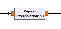
Gnu Radio provides several blocks that allow you to change the sample rate. Here are some examples:

Gnu Radio and Sample Rate
When looking at a Gnu Radio flowgraph, the sample rate is always set by connected hardware or "Throttle" block. This is the baseline for the sample rates for the rest of the flowgraph. The sample rates of any other blocks in the flowgraph will depend on this base sample rate and any decimation (reduction in sample rate) or interpolation (increase in sample rate) from that hardware source block to the block in question. If there are two hardware blocks, such as a SDR as a source and an audio sink, then there could be problems if the different decimation or interpolation values in between don't match up.
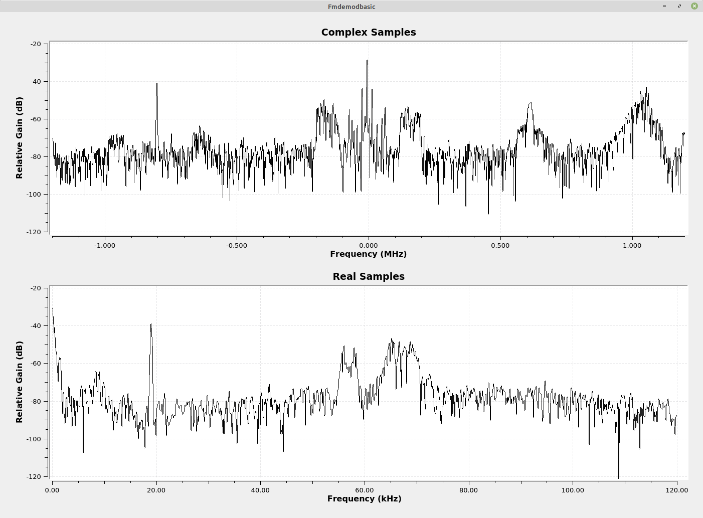
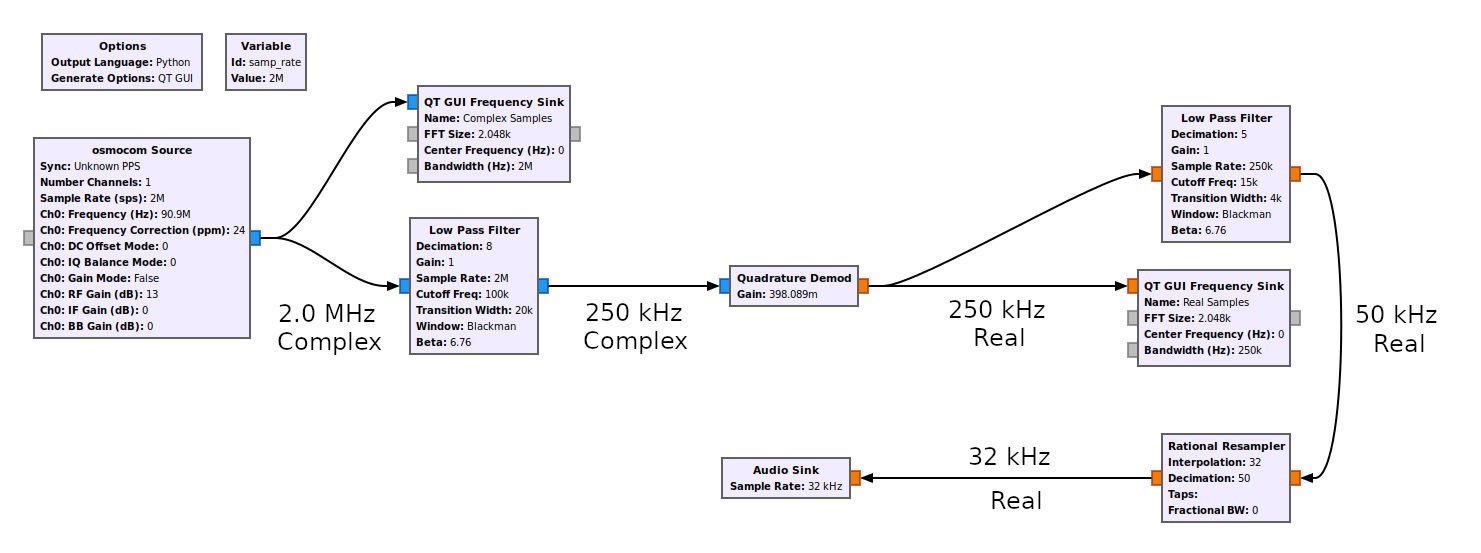
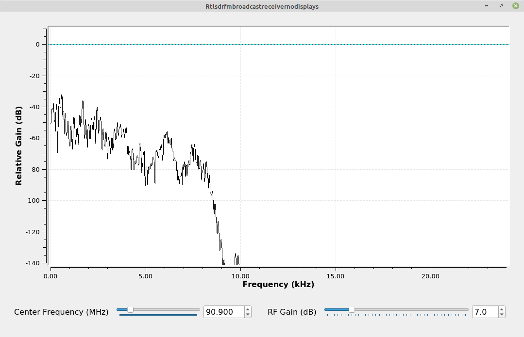
Let's take a quick stroll through a flowgraph. We'll start with the flowgraph used to make the spectra shown above.
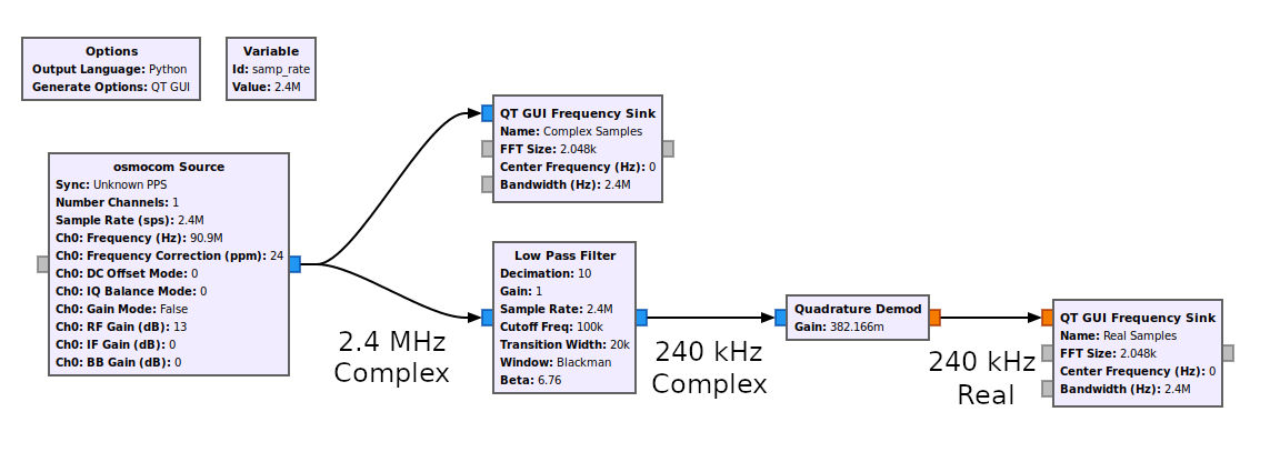
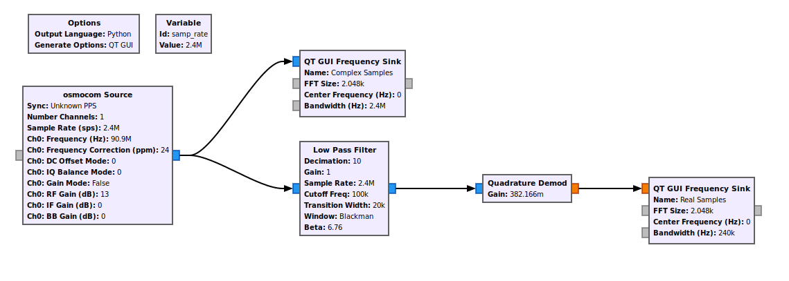
The first block is the source. In this case, it's a piece of hardware, a RTL-SDR. The sample rate setting for this block is 2.4 MHz, and it sets the sample rate of its digitizer. This means the RTL-SDR connected to my computer is running at a sample rate of 2.4 MHz. Because it controls a piece of hardware, this block sets the sample rate for the rest of the flowgraph.
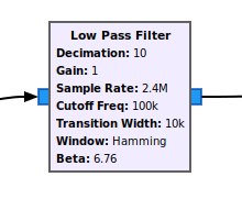
The output complex samples go to a lowpass filter. The two, key settings here (with respect to the sample rate) are "Sample Rate" and "Decimation". Here's the thing about the "Sample Rate" setting. It's actually meaningless for the actual sample rate. Digital filters do not operate on absolute numbers. They operate on ratios, specifically the ratio of the cutoff frequency to the sample rate, or the ratio of the transition width to the sample rate. That's all that value "Sample Rate" in this block is used for. It's used to calculate the ratios for the various values (cutoff frequency, transition width). Those ratios are used to calculate the filter tap values for the filter itself. Again, it has absolutely no effect on the actual sample rate going through the block. I could set this sample rate value to 1. Then, so long as I set the "Cutoff Freq" and "Transition Width" values such that the ratios are still the same (1/24 for the cutoff frequency, 1/120 for the transition width), the filter will still operate exactly the same. The one value that does affect the sample rate is the "Decimation" value. Decimation means "reduce the sample rate". The value of "10" here means "keep 1 sample out of every 10". The rest? Throw them away. Trash'em. Get rid of 'em. The result is an output sample rate that is 1/10th of the input sample rate.
The next stop for our sample stream is the "Quadrature Demod" block. This is the frequency demodulator. It doesn't affect the sample rate, per se, but it does affect the samples. It turns the input complex samples into an output of real samples. The result? Our available bandwidth just dropped by 1/2. The sample rate at the input and output are the same, but since the output is real samples, it only has an available bandwidth of 1/2 of the input sample rate.
The last block is just a frequency sink. It doesn't have a sample rate setting, but it does have a setting for "Bandwidth". That is nothing more than the sample rate at the input of the block. Further, just as with the "Sample Rate" setting, it has absolutely no affect on the actual sample rate of the block. It uses the "Bandwidth" setting to properly scale the horizontal (frequency) axis of the graph.
Let's sum up the parts that actually affect the sample rate of this flowgraph. The first is the "osmocom Source" block. It sets the sample rate for the rest of the flowgraph. The "Low Pass Filter" block uses decimation to lower the sample rate. That decimation value is the only setting in that block that actually affects the sample rate. The "Quadrature Demod" block does not affect the sample rate, but it does affect the samples (turns them from complex into real). That's it. None of the other components have any affect on the sample rate.
With respect to Gnu Radio, there are a couple of things that you must bear in mind:
- There must be either a piece of hardware used in the flowgraph (SDR, audio card) or a "Throttle" block. That piece of hardware or that throttle block will set the sample rates of the rest of the flowgraph. For example, if I have a flowgraph using a RTL-SDR, then the sample rate I set for the RTL-SDR will drive the sample rates of the rest of the flowgraph. If you don't have a physical piece of hardware connected and are using the "Throttle" block instead, then the throttle block will be the driver for the rest of the flowgraph.
- You must manually set all sample rates in Gnu Radio. There's nothing automatic about any of the sample rate settings. You, the user, have to ensure that all of the sample rates in your flowgraph, whether in the hardware, filters, demodulators, sinks, or whatever, are set properly. Gnu Radio does not check that they're set correctly. You have to make sure that all of the sample rates between components line up. For example, if the input to a lowpass filter is 500 kHz, and you need the output to be 100 kHz, then you have to set the decimation value in the filter to 5. Again, that's up to you to do that. If you do not set it correctly, your flowgraph will either not run, or it will not run correctly.
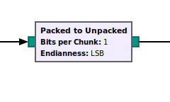
- Some things will affect the sample rate that you may not think of. Look at the "Packed to Unpacked" block. It has no interpolation value, but it still interpolates the input sample stream. An "Unpacked to Packed" does just the opposite; it decimates the input sample stream, but there is no explicit decimation value. There are probably others. I've not gone through every, possible block. Yet.
- The only blocks that have the value "Sample Rate" that actually affect the sample rate are hardware source blocks and hardware sink blocks. Hardware source and sink blocks are ones that control actual hardware connected to your computer. For example, the "osmocom Source" and "RTL-SDR Source" blocks are hardware that connect to the computer. Gnu Radio then controls those pieces of hardware using their respective source blocks. The same with sinks. The "UHD:USRP Sink" block and the "Audio Sink" (which controls the audio card on your computer) are both controlled by their respective sink blocks, and have "Sample Rate" values. In these cases, the "Sample Rate" setting actually affects the sample rate of the flowgraph. For all of the other blocks used in a flowgraph, their value for "Sample Rate" only affects some aspect of that block, such as with the already-mentioned filtering or the scaling of the frequency axis in the frequency sink block. They don't actually affect the sample rate.
- Any entered interpolation or decimation values must be integers. As stated above, digital processing does not work on partial samples. Ever. You cannot process 2.4 samples or 10.83 samples. Digital processing always works on an integer number of samples. Same applies to changing the sample rate through decimation or interpolation. These must be integers. In Gnu Radio, green entry boxes indicate "This must be an integer value". If you try to put a decimal value of any kind in such a window, Gnu Radio will give you an error. Your flowgraph will not run.
- If you have both a hardware source and sink, you need to ensure that the sample rates for both match with the rest of the flowgraph. One of the biggest issues I see in "Hey, Gnu Radio people! My audio sounds like crap with my receiver! HELP!" It's almost invariably due to the sample rates between two piece of hardware not matching up. I have an example of a system that does match the sample rates below. There are other, possible reasons that such a flowgaph won't work properly (the audio card doesn't work with the desired sample rate, the computer cannot process the flowgraph fast enough). But if the sample rates don't match up across the flowgraph, it won't work properly regardless.
Some Other Sample Rate Examples

Some Problems of Incorrect Sample Rates in Gnu Radio
And what are some of the problems that might arise if the sample rate is incorrect? Here's a sampling (heh) of possible problems when the sample rate is incorrect:
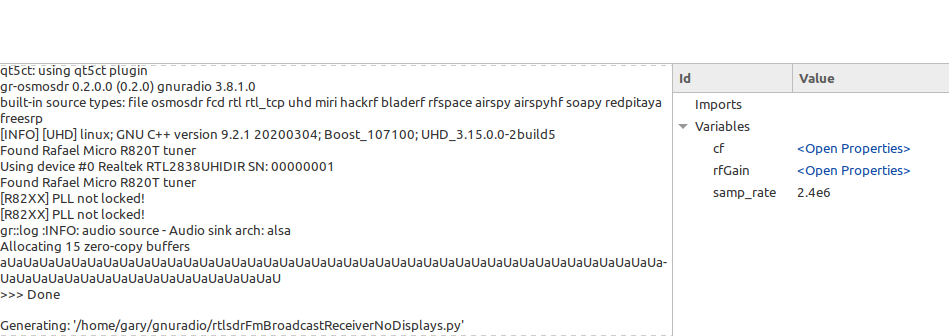
- Underruns or overruns to hardware: Gnu Radio provides a small window, typically in the lower, left corner that shows a running log of what is happening. "OOOOOOOO" and "UUUUUU" represent overruns and underruns, respectively. A few such overruns or underruns when first running a flowgraph are normal. But if they occur constantly while the flowgraph is running, then there's a problem. An overrun condition means that the hardware is being sent too many samples. An underrun condition is the opposite. An underrun to a sink means it is not being fed enough samples. A classic example of this is listening to the audio output of a receiver and hearing skips or pauses.
- The signal output has its frequencies all wrong: This is more likely if you're using a file source. Reading samples from a file, such as using the "File Source" block, is not the same as reading from a piece of hardware. Yes, a hard drive is hardware. Gnu Radio doesn't consider it "hardware whose sample rate I have to respect". So, if you're reading samples from a file on your hard drive, you have to manually set the sample rate to that in which the file was created. Gnu Radio does not store any metadata when you create a file using the "File Sink" block. There is no information on the sample rate used to create the file stored in the file itself. You have to do that manually. I typically put the sample rate as part of the file name. Since you simply have a file full of samples (real or complex), they can be read out at whatever rate you want. So long as all of the sample rates in your flowgraph match up, it will run fine. But the output will be... wrong.
- Time and frequency graphs will be wrong: These two types of displays, such as the "QT GUI Time Sink" and "QT GUI Frequency Sink", are the workhorses of Gnu Radio, in my opinion. But if the sample rates they are set to are incorrect, then they'll provide incorrect time or frequency information. Here's the good part about these displays: They do not affect sample flow through a flowgraph. This means that, if you set the sample rate incorrectly for a time display, you'll simply get incorrect time information from that display.
- Filters will be improperly set: In the digital world, filters do not work on absolute numbers. They work on ratios. The ratio is between the value of the parameter (passband edge frequency, stopband edge frequency, transition width) and the sample rate. If the sample rate setting for a filter is not set properly, then the ratio will be wrong. If the ratio is wrong, then the filter parameters will be wrong. If the filter parameters are wrong, then the filter will not filter in the way you want. It will still filter, but the filtered parts will either be too much, or too little.
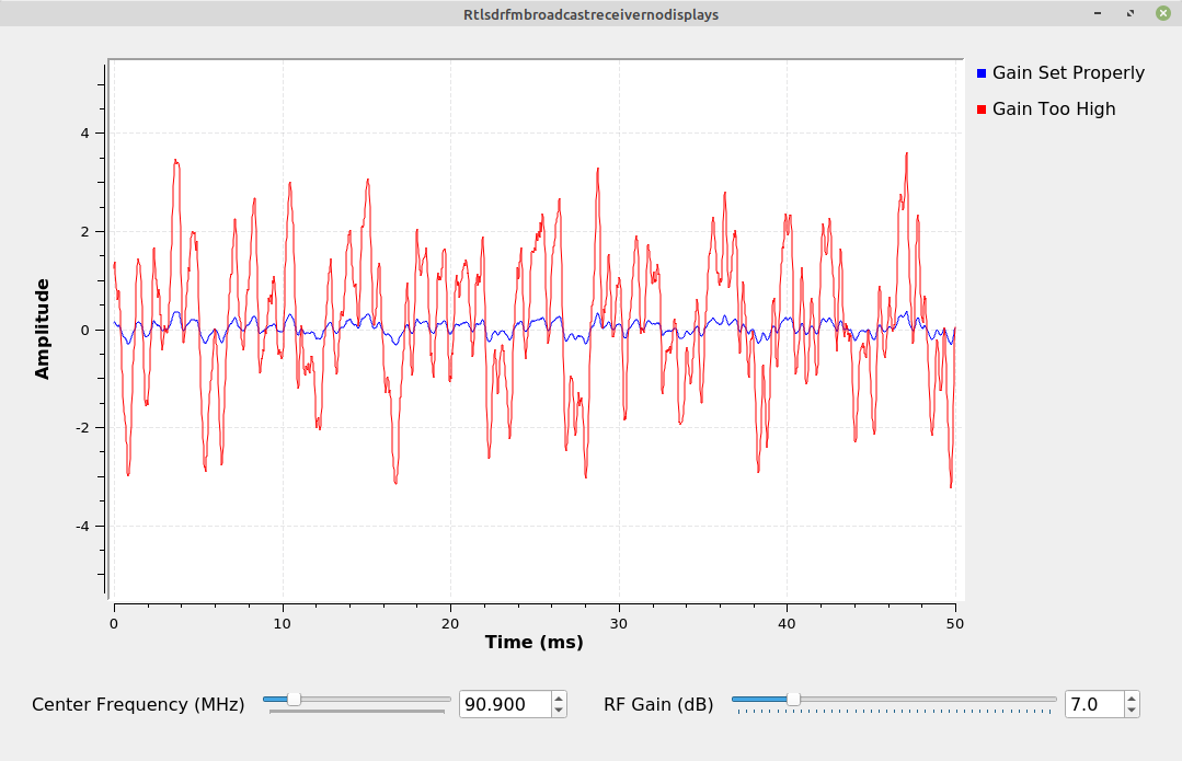
- The output of the quadrature demodulator will be too loud or too quiet: The Gnu Radio quadrature demodulator block, the primary one that I use for frequency demodulation, requires a "Gain" setting. That setting is based in part on the sample rate. If the sample rate is set improperly, then the gain will be wrong. The result is that the output of the quad demod block will be too quiet, or too loud.

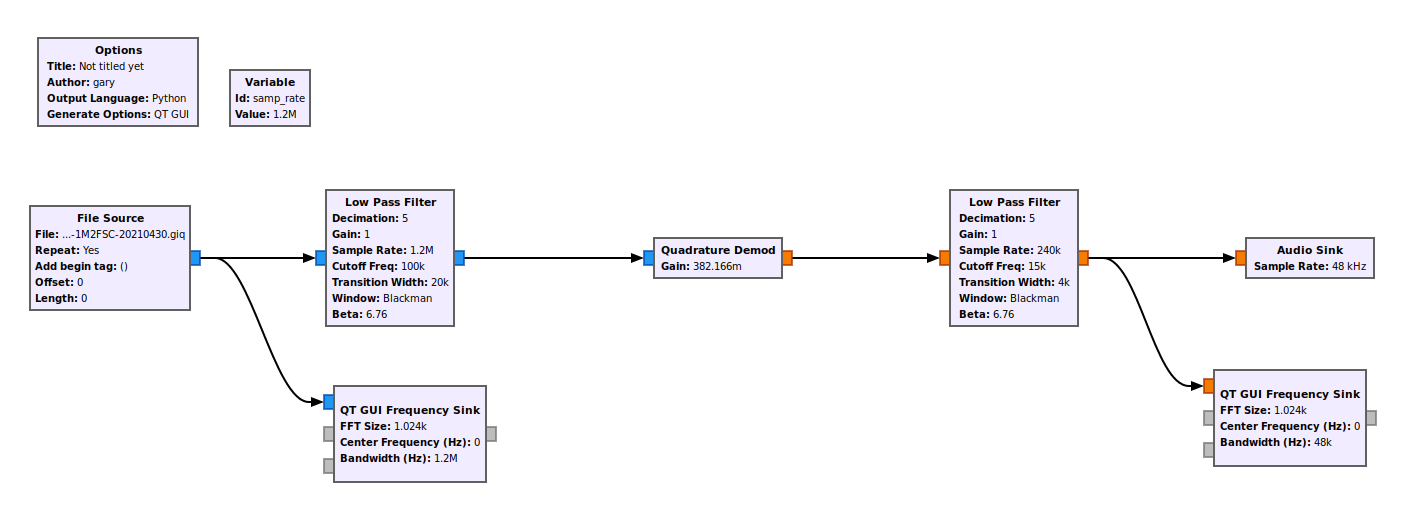
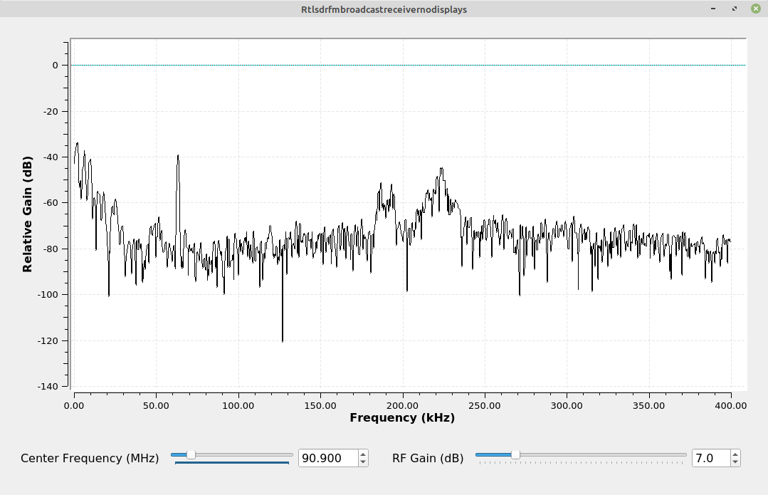
| This is the demodulated audio from a FM broadcast station. It was collected as a file using "File Sink" and read out with the correct sample rate. | |
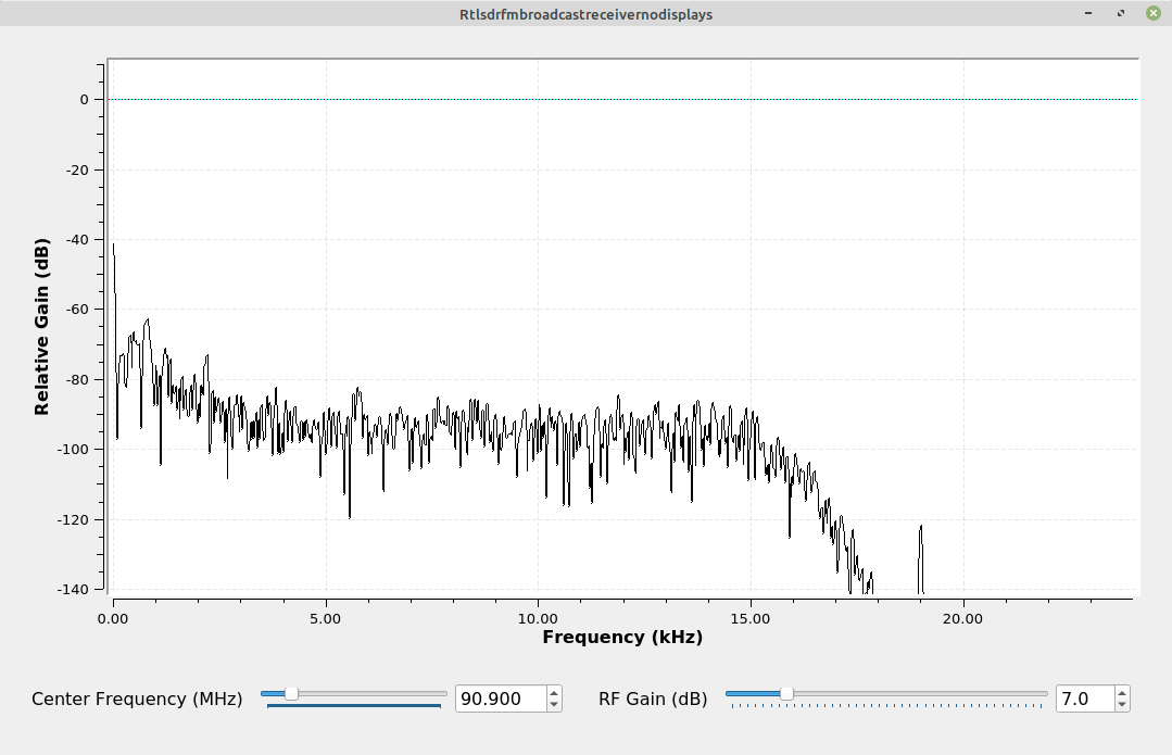
| This is the demodulated audio from the same FM broadcast station as above. In this case, the file was read too low (was collected at 2.4 MHz, but read out at 1.2 MHz). |
Some Last Key Points
Here are a few, key points with respect to the sample rate of a digital system:
- Digitized analog signals have a minimum required sample rate. This is the Nyquist criterion. Regardless of the sample type, real or complex, there is a minimum sample rate that must be maintained in order to avoid aliasing. For real samples (which Gnu Radio calls "floats"), the minimum sampling rate must be at least twice the bandwidth of the analog signal. For complex samples, the minimum sampling rate must be at least equal to the bandwidth of the analog signal. An important point to remember here? RF signals are always analog. When you use a SDR to process an RF signal, one of the things it is doing is digitizing the incoming RF signal and making it digital. If the original RF signal has a bandwidth of 48 kHz, then that bandwidth drives the minimum sample rate you need to digitize it properly without aliasing.
- Sample rates must be kept low enough to allow for the computer upon which the flowgraph is operating to keep up. Analog signals have a minimum sampling rate (Nyquist). The maximum is really whatever the hardware can handle. CPUs and GPUs can only process so many samples in a set time. Buses can only move so many bits per second. Both of these things, combined with how efficiently the software is written, determines how many samples per second can be processed.
- Hardware can only handle certain sample rates. SDRs come equipped with analog-to-digital converters (input) or digital-to-analog converters (output). These can only handle certain sample rates. For example, most RTL-SDRs require the sample rate to be set either between 225 - 300 kHz, or between 900 kHz - 3.2 MHz. Further, the 3.2 MHz upper limit is what the hardware says it can handle. In actuality, most RTL-SDRs start to drop samples with rates above 2.4 MHz. Audio cards have very limited sample rates. For example, the audio circuitry on my computer is on the motherboard. According to a short Linux command on the command line ("grep -P 'rates|bits' /proc/asound/card0/codec\#0"), my audio card can only handle 32, 44.1, 48, 88.2, 96 and 192 kHz. Any other rate will cause a problem.
File Source and Sinks and Gnu Radio
Gnu Radio makes it possible to record signals. This is the "File Sink" block. You can then play back those signals using the "File Source" block. Here's the thing about these blocks. They're not hardware. There's no sample rate entry. Gnu Radio does not record any sample rates when the files are made. A file sink, used to create a file of samples, does not record any metadata of any kind. This means you have to record that yourself. I typically put the sample rate and sample type (real, complex) as part of the file name.
If you take the output of a hardware source and send it directly to a "File Sink" block, that block will write those samples to a file. Here's the cool part. Reading those samples back will be exactly as if they came directly off of the hardware source originally. There's absolutely no difference.

There's one other point I want to make about file sources. Because they are not hardware, you cannot use them to set the sample rate for the flowgraph. This means that, if you don't have another piece of hardware in the flowgraph, such as an audio sink, then you need to put a "Throttle" block in the flowgraph.
You can record a file at one sample rate, and read it back at a different rate. Gnu Radio will have no clue that anything is wrong. Any processed signals from a file that is read back at the wrong rate will either not process correctly, or it will provide a wrong output. Again, because Gnu Radio sets all of the sample rates manually, it's up to you to ensure that they're all correct.