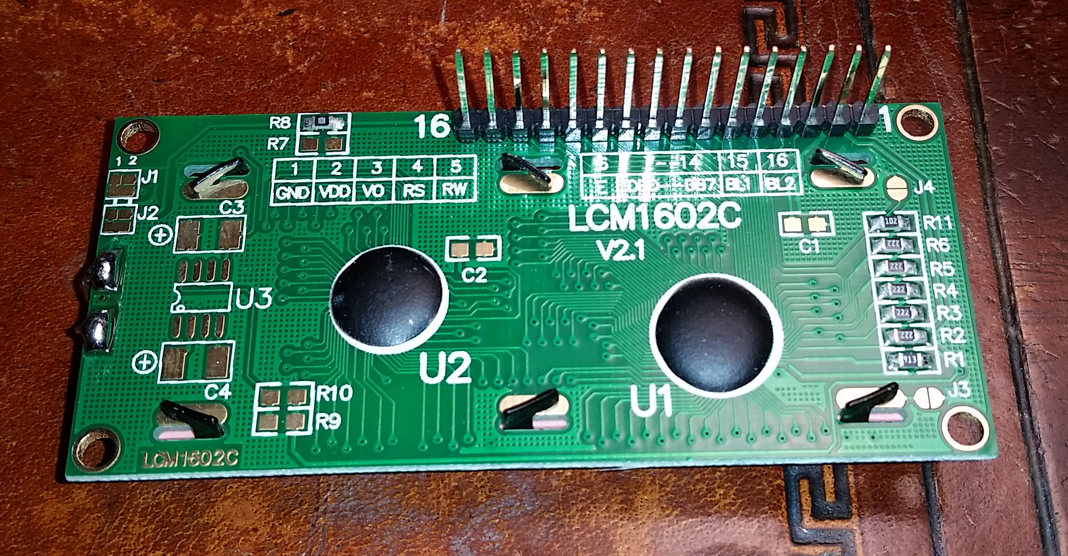
Understanding the LCM1602C LCD Display: Programming with the Arduino, Part 1

Gary Schafer, 1 November 2014

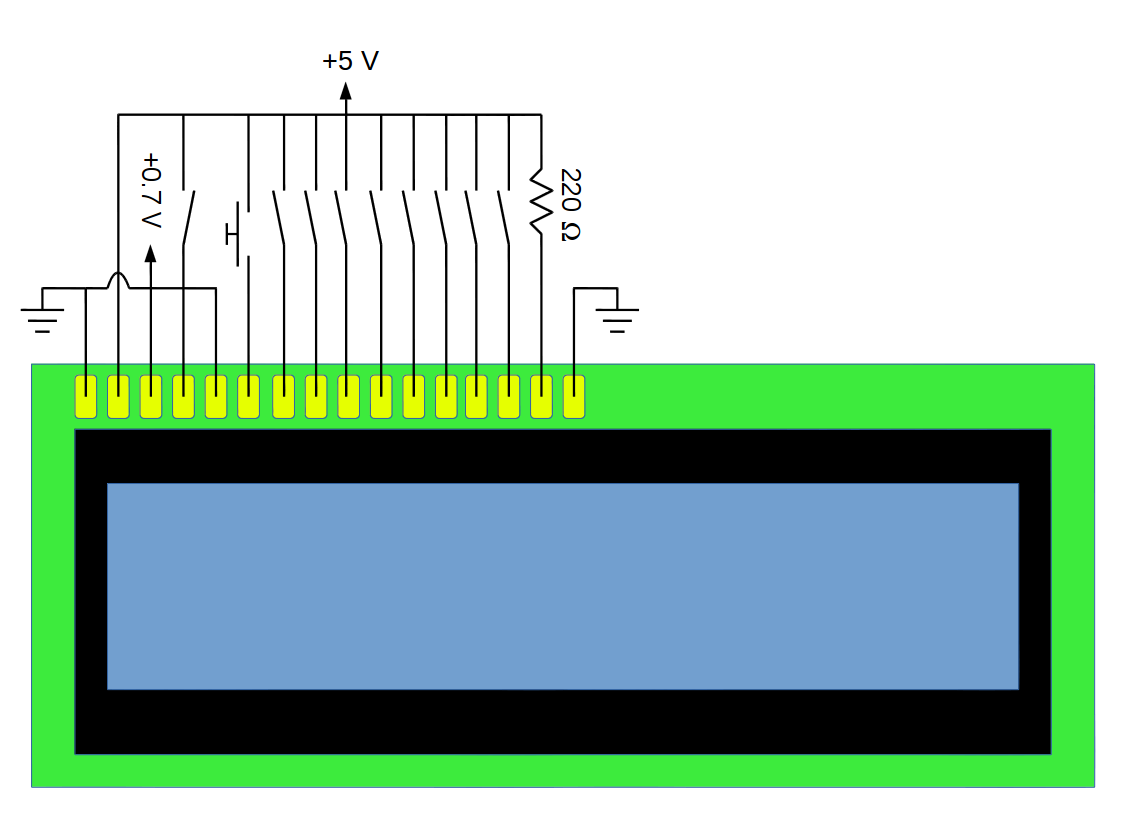
In my previous article, I walked through how tying the various connections on the LCD between ground (GND) and +5V would program the LCD to display pretty much anything you wanted. I'll even point you towards a video tutorial by RC Tractor Guy that actually demonstrates how you can use simple switches to program the LCD. Frankly, it explains things a lot better than I do.

As you might have guessed, it would take a looooooong time to use such a basic circuit to program an LCD. It would also be time-consuming to make any changes to the LCD display. This means you need something that you can change more easily. I'm going to use an Arduino to do just that. I have an Arduino Uno (that has an Ethernet shield mounted on top) to do just that.

I want to start from the beginning and take this a single step at a time. In my last post, I explained that programming the Hitachi LCD is nothing more than connecting certain inputs to either ground or +5V, then connecting the EN line to +5V, then back to ground. That's exactly what RC Tractor Guy demonstrates in his video. Using the Arduino, we're going to replace the physical switches with the basic Arduino commands digitalWrite and delay. Yes, I realize that there is an entire library of Arduino code that does this with a lot less coding. We'll get there. Be patient.

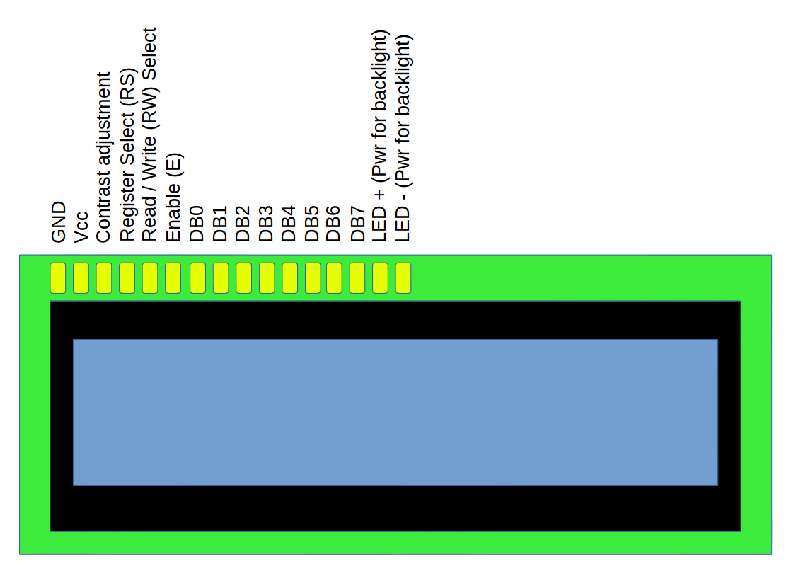
The connections I'm using are straight out of the Arduino Starter Kit book. Specifically, on the LCD:

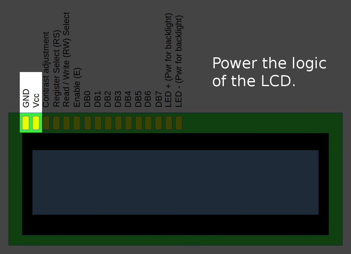
  • Pin 1 is connected directly to ground.
  • Pin 2 is connected directly to +5V. (NOTE: This, in turn, comes directly from the +5V output of the Arduino Uno.)
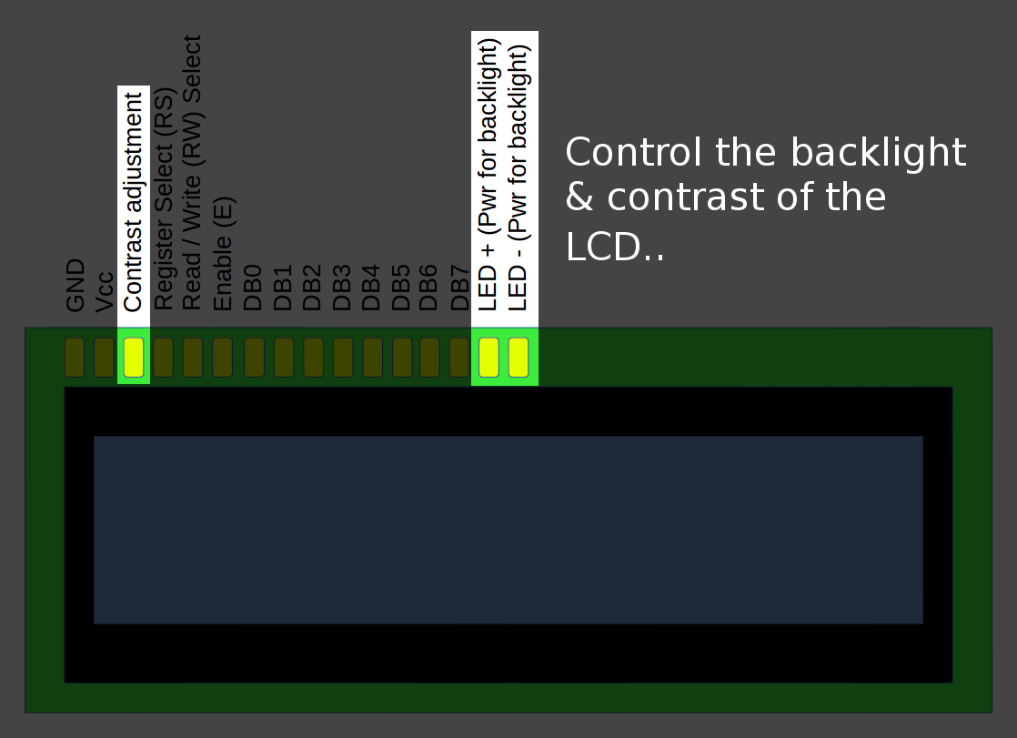
  • Pin 3 is connected to the middle pin of the 10k potentiometer, and is used to adjust the contrast of the LCD.
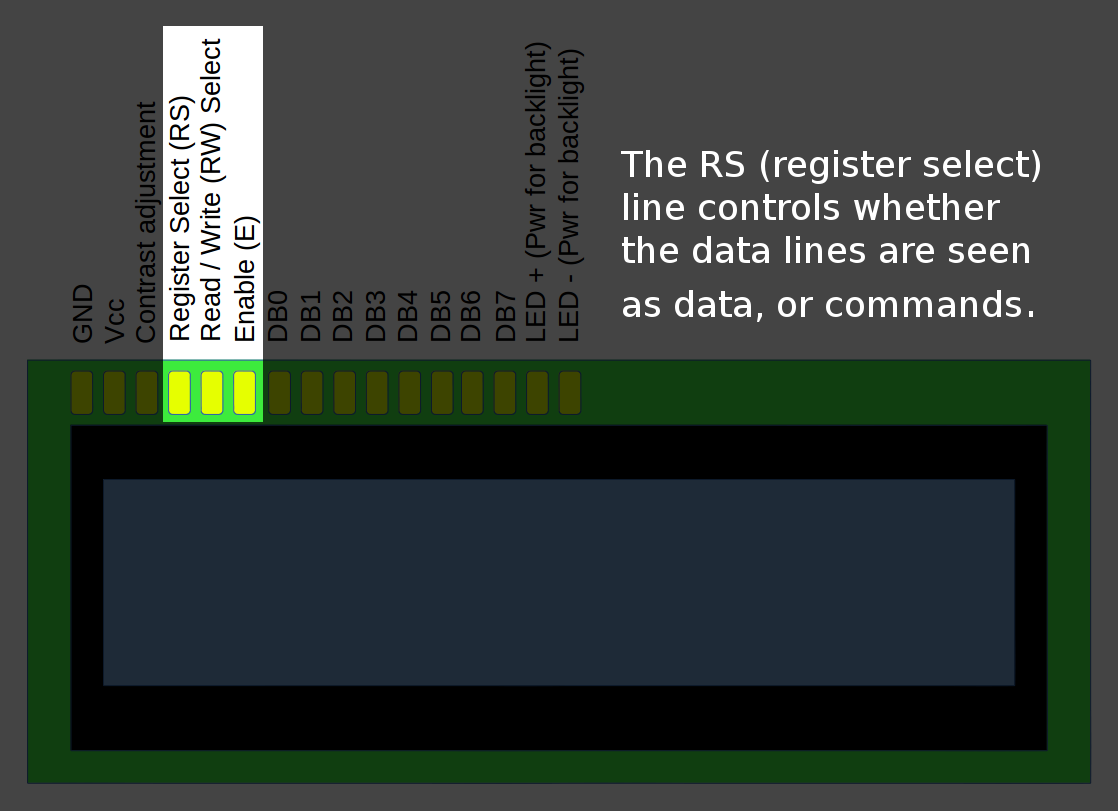
  • Pin 4 (RS or "register select") is connected to pin 12 on the Arduino Uno.
  • Pin 5 (RW or "read/write") is connected directly to ground. By doing this, we're saying that we're only going to write to the LCD, not read anything from it. Which is fine. We just want to put text onto the LCD, not read anything from it anyway.
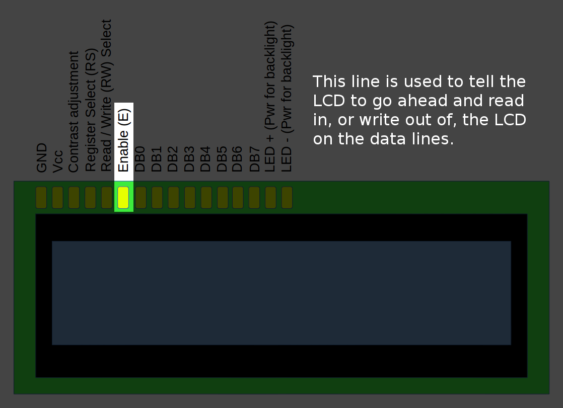
  • Pin 6 (EN or "enable") is connected to pin 11 on the Arduino Uno.
  • Pins 7 - 10: Not connected.
  • Pin 11 on the LCD is connected to pin 5 on the Arduino Uno.
  • Pin 12 on the LCD is connected to pin 4 on the Arduino Uno.
  • Pin 13 on the LCD is connected to pin 3 on the Arduino Uno.
  • Pin 14 on the LCD is connected to pin 2 on the Arduino Uno.
  • Pin 15 is connected to one end of a 1k resistor, and the other end of the resistor is connected to +5V.
  • Pin 16 is connected directly to ground.

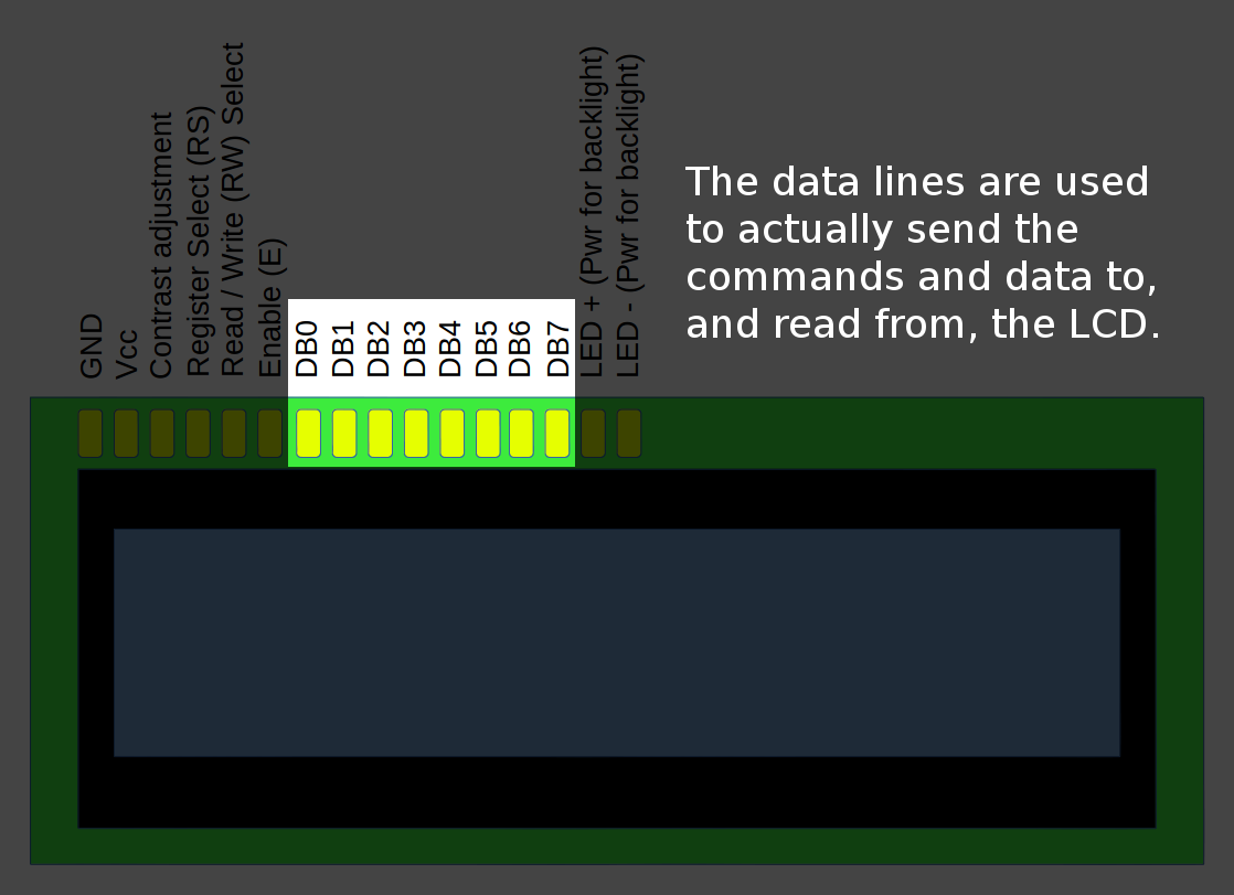
With everything connected, the next part is to code the commands for the Arduino. For this, I'm only going to need to code for six connections. These are the RS (register select) line (pin 12 on the Arduino), the EN (enable) line (pin 11 on the Arduino), and the four data lines (pins 2 - 5 on the Arduino). Everything else is already set.

All I have to do now is to set the commands on the four data lines (again, pins 2 - 5 on the Arduino), set the RS line (pin 12 on the Arduino), then pulse the EN (enable) line on the Arduino HIGH, then LOW. Using the chart from the previous post, in which a "1" means "HIGH" and "0" means "LOW", I get

CommandRSD7D6D5D4
Function set (4-bit, 2-lines, 5x8 font), high-order bits.00010
Function set (4-bit, 2-lines, 5x8 font), these particular high-order bits have to be repeated this one time.00010
Function set (4-bit, 2-lines, 5x8 font), low-order bits.01000
Turn the display and cursor ON, and set the cursor to blinking, high-order bits.00000
Turn the display and cursor ON, and set the cursor to blinking, low-order bits.01100
Set the entry mode, with the cursor incrementing and the display not shifting, high-order bits.00000
Set the entry mode, with the cursor incrementing and the display not shifting, low-order bits.00110
Change the cursor position to the 2nd line, 4th position from the left, high-order bits.01100
Change the cursor position to the 2nd line, 4th position from the left, low-order bits.00011
Enter a character "H" into the display at the current cursor position, high-order bits.10100
Enter a character "H" into the display at the current cursor position, low-order bits.11000
Enter a character "e" into the display, high-order bits.10110
Enter a character "e" into the display, low-order bits.10101
Enter a character "l" into the display, high-order bits.10110
Enter a character "l" into the display, low-order bits.11100
Enter a character "l" into the display, high-order bits.10110
Enter a character "l" into the display, low-order bits.11100
Enter a character "o" into the display, high-order bits.10110
Enter a character "o" into the display, low-order bits.11111

This should result in the following image:

This is programming the LCD at its most basic, nothing more than connecting the various lines to either +5 V or ground, in a particular sequence. It's "assembly language for the LCD". (Okay. Not really. We're not moving bits around registers. But I hope you get the point.) Many Arduino-to-LCD projects use only four data lines (4-bit transfers), such as this one and this one. Regardless of how its programmed, whether with an Arduino or with a Raspberry Pi running through its GPIO ports, ultimately, the logic being sent to the LCD must be that as shown above. For example, if you're programming the Arduino to display the letter "H", then it's sending the same two 4-bit transfers as shown when you sent the letter "H" in the table above. It's just that you've now created an abstract layer in between you and the LCD. You told the program "Display the letter 'H'", the program figured out what logic needs to be sent to the LCD (set RS line HIGH, set data lines D7-D0 to 01001000, then flash the EN line one time), then sent it. It's that straightforward.

In Part 3, we'll cover creating special characters.

Understanding the LCM1602C LCD Display, Part 2

Gary Schafer, 1 November 2014

In my first post, I covered the basics of programming the LCD display. That programming used all eight data lines. The great thing about the HD44780 standard is that it also provides for the ability to use only four data lines to program it. I'm going to cover this 4-bit programming in this post.

The specification explicitly states that 4-bit programming should use data lines D7 - D4. The data and instruction commands are still 8-bits long. This means that each data transmission or instruction requires two EN cycles, meaning two 4-bit transfers. The specification states that the high-order bits be sent first, and the low order bits second. There's also a little-tidbit that is not well explained in the specification. It's that, in order to set-up the LCD for 4-bit transfer, the first command needs to be the function set command, except that the first 4-bit transfer has to be repeated. Also, remember that the EN (enable) line has to be cycled HIGH, then LOW between each 4-bit transfer.

CommandRSD7D6D5D4
Begin initializing the LCD.00011
Forced delay between first and second steps of initializing the LCD.Delay at least 4.1 msec.
Second step of initializing the LCD.00011
Forced delay between first and second steps of initializing the LCD.Delay at least 100 usec.
Third time to finish initializing the LCD.00011
Set the LCD to 4-bit transfers.00010
Set the LCD to 4-bit transfers (repeat).00010
Function set (4-bit, 2-lines, 5x8 font), low-order bits.01000
Turn the display and cursor ON, and set the cursor to blinking, high-order bits.00000
Turn the display and cursor ON, and set the cursor to blinking, low-order bits.01111
Clear the display, high-order bits.00000
Clear the display, low-order bits.00001
Set the entry mode, with the cursor incrementing and the display not shifting, high-order bits.00000
Set the entry mode, with the cursor incrementing and the display not shifting, low-order bits.00110
Change the cursor position to the 2nd line, 3rd position from the left, high-order bits.01100
Change the cursor position to the 2nd line, 3rd position from the left, low-order bits.00010
Enter a character "H" into the display at the current cursor position, high-order bits.10100
Enter a character "H" into the display at the current cursor position, low-order bits.11000
Enter a character "e" into the display, high-order bits.10110
Enter a character "e" into the display, low-order bits.10101
Enter a character "l" into the display, high-order bits.10110
Enter a character "l" into the display, low-order bits.11100
Enter a character "l" into the display, high-order bits.10110
Enter a character "l" into the display, low-order bits.11100
Enter a character "o" into the display, high-order bits.10110
Enter a character "o" into the display, low-order bits.11111
Enter a character "," into the display, high-order bits.10010
Enter a character "," into the display, low-order bits.11100
Enter a "space" character into the display, high-order bits.10010
Enter a "space" character into the display, low-order bits.10000
Enter a character "w" into the display, high-order bits.10111
Enter a character "w" into the display, low-order bits.10111
Enter a character "o" into the display, high-order bits.10110
Enter a character "o" into the display, low-order bits.11111
Enter a character "r" into the display, high-order bits.10111
Enter a character "r" into the display, low-order bits.10010
Enter a character "l" into the display, high-order bits.10110
Enter a character "l" into the display, low-order bits.11100
Enter a character "d" into the display, high-order bits.10110
Enter a character "d" into the display, low-order bits.11100
Enter a character "!" into the display, high-order bits.10110
Enter a character "!" into the display, low-order bits.11100

This should result in the following image:

This is programming the LCD at its most basic, nothing more than connecting the various lines to either +5 V or ground, in a particular sequence. It's "assembly language for the LCD". (Okay. Not really. We're not moving bits around registers. But I hope you get the point.) Many Arduino-to-LCD projects use only four data lines (4-bit transfers), such as this one and this one. Regardless of how its programmed, whether with an Arduino or with a Raspberry Pi running through its GPIO ports, ultimately, the logic being sent to the LCD must be that as shown above. For example, if you're programming the Arduino to display the letter "H", then it's sending the same two 4-bit transfers as shown when you sent the letter "H" in the table above. It's just that you've now created an abstract layer in between you and the LCD. You told the program "Display the letter 'H'", the program figured out what logic needs to be sent to the LCD (set RS line HIGH, set data lines D7-D0 to 01001000, then flash the EN line one time), then sent it. It's that straightforward.

In Part 3, we'll cover creating special characters.

Understanding the LCM1602C LCD Display, Part 1

This is the front of the LCM1602C display. The white, triangular part on the right end is the location of the LED backlight.
This is the underside of the display. The long pins will plug into a breadboard.
This is the pin-out for the LCM1602C LCD display.
This is a very basic set-up that can be used to program the LCD.
This is the basic set-up, with the switches set to send the FUNCTION SET command. This specific command will tell the LCD that it's set for 8-bit data transfers, 2-lines of display, and a 5x8 point font.

Gary Schafer, 1 November 2014

This particular post will cover a bit of technology that most people simply know as "the LCD display". I'm not talking about the computer monitor type of LCD display; no, I'm talking about that small screen on many common pieces of electronics, the one that looks like this.

I'm going to talk about the LCM1602C LCD. The purpose of this post is to get away from a lot of the esoteric "how tos" of this particular display. Ya see, this display is based on the Hitachi HD44780 LCD controller. The nice thing about that is the specifications are readily available. The problem is that the specifications are not readily understood. Yes, I believe that this is an example of "lost in translation".

If you read many of the "how tos" for this display, you'd think you have to know how to program an Arduino, or how to program in C language, to program this particular display. I'm here to tell you that you can actually do it with nothing more than some wire and a power supply for the display. Mind you, it will be a lot of work to program it this way, but it's definitely doable. It will also provide an understanding of what the Arduino, or Raspberry Pi, or C language, must be doing in order to program the display.

Let's talk about the display first. This particular display is a 16 character by 2-line display. Its memory can hold up to 80 characters, 40 on each line of the display. The actual part that displays the characters can only show 16 characters across at any one time. Using the SHIFT command, you can move the part of the lines that are displayed.

There are 16 connections you'll use to power and program the LCD. These connections can be sorted, which I've done as follows:

Let's talk about wiring up some basics on this not-so-beastly beast. Start with the logic power, which is pins 1 (GND) and 2 (Vcc, which for this board is +5 V). Since this board, which according to its specification, is powered by +5 V, that makes it ideal to power using a USB line. I used an Arduino Uno, which connects to a USB line and provides a 5 V output to power external devices. I'd also bought a couple of small mini-B USB connector break-out boards from Sparkfun to provide power for various 5 V projects.

You can do all of the wiring and logic with nothing more than some wire and switches, as you can see in this Youtube video. One issue of such a set-up is that of using a manual, human-operated switch on the EN (enable) line. The problem is that such switches create a condition called "bounce", which causes inputs to repeat.

I used an Arduino to drive my LCD display simply so that I could drive the various logic lines. I didn't use any of the specialized Arduino libraries for driving a LCD; instead, I simply used the standard digitalWrite command to send the commands and data. The digitalWrite command merely sets the targetted output pin to either 0 V (GND, or LOW) or to +5 V (HIGH). This is equivalent to opening (LOW) or closing (HIGH) a switch. The difference is that using the Arduino means you don't have the "bounce" problem. The hard part is that you have to code each HIGH and LOW of each line.

To simplify the steps, I'm going to use a table in which each HIGH is replaced by a 1, and a LOW is replaced by a 0. After each step, the EN (enable) line on the system has to be set HIGH, then LOW. This tells the LCD to read in the data or instructions.

CommandRSD7D6D5D4D3D2D1D0
Function set (8-bit, 2-lines, 5x8 font)000111000
Turn the display and cursor ON, and set the cursor to blinking.000001111
Set the entry mode, with the cursor incrementing and the display not shifting.000000110
Change the cursor position to the 2nd line, 4th position from the left.011000011
Enter a character "H" into the display at the current cursor position.101001000
Enter a character "e" into the display.101100101
Enter a character "l" into the display.101101100
Enter a character "o" into the display.101101111

This should result in the following image:

If you happen to be using the normal LCD library for an Arduino, or programming the LCD using a C or C++ based system, then when you program it to, say, show the letter "H", or program it to have the cursor blink, then your programming has to be setting the various lines in a manner similar to what we just did above. Think of this as "assembly language for the LCD".

We'll continue this in Part 2.

Here's a Random Fact...