
Random Quote Board
Hak5, Gnu Radio & Their Frequency Demodulator - Why Did It Work?
I've gone down the rabbit hole of frequency demodulators using software defined radios (SDR) just about as deep as I care. Part of that trip took me to a Youtube video by Hak5, hosted by Darren Kitchen and Shannon Morse, demonstrating how to create a FM receiver using a SDR. Despite the fact that the video is now over 6 1/2 years old, I've watched it a few times now. But I still can't understand something. Why did it work?
Hear me out. It should not have worked. There are two issues with their graph that says (to me) that it should not have worked. I'm not berating them. I'm asking out of a curiosity of watching someone do something, thinking, "That won't work.", then watching in astonishment when it actually works.

Let's dive in, and I'm going to develop a hypothesis as to why it worked along the way.
The Center Frequency Conundrum
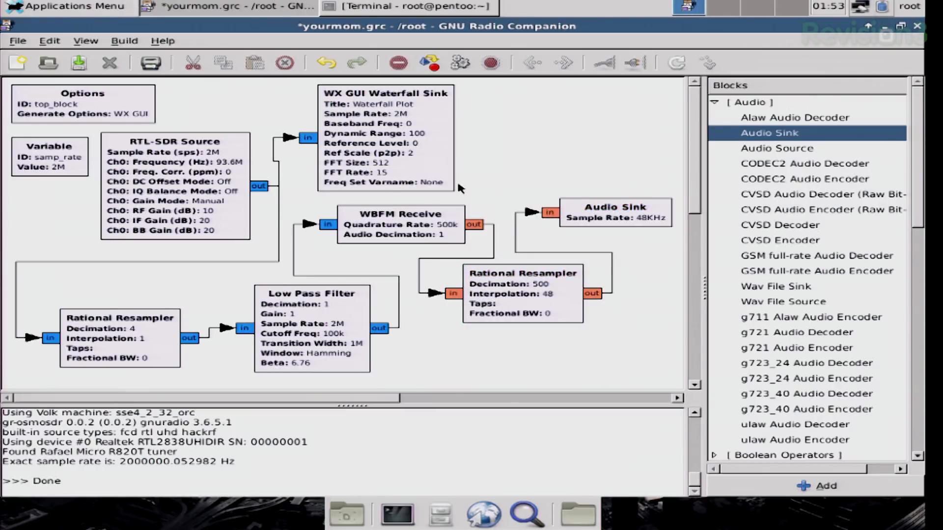
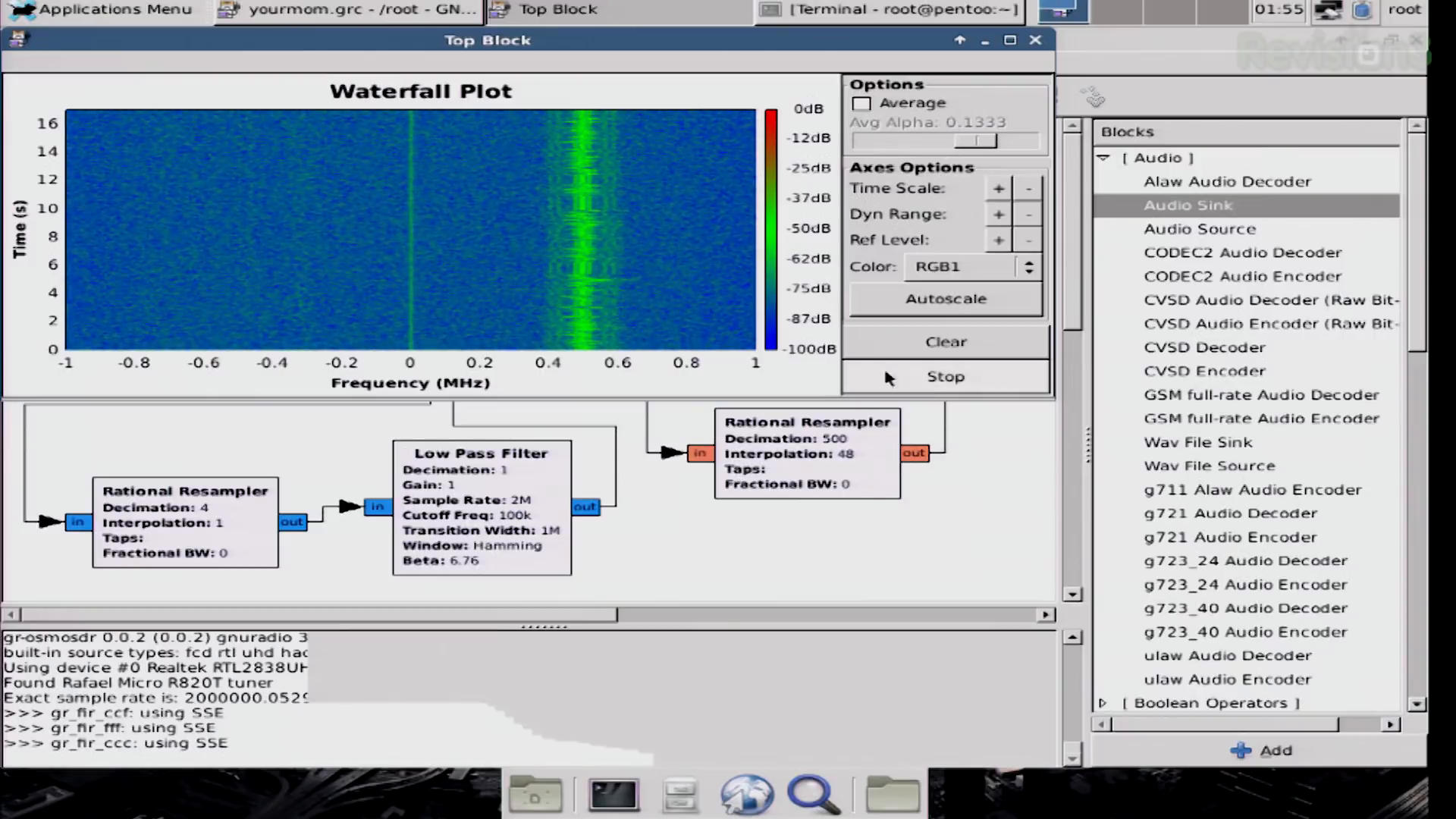
They first created a basic spectrum analyzer. They set the center frequency of their Realtek RTL-SDR to 93.6 MHz, with a 2 MHz sample rate. Here's the first, major problem. FM broadcast stations in the US operate on odd frequencies. They start at 87.5 MHz, and run all the way up to 107.9 MHz, with 200 kHz steps in between. They're tuned to 93.6 MHz, which is not the center frequency for a US FM broadcast station.
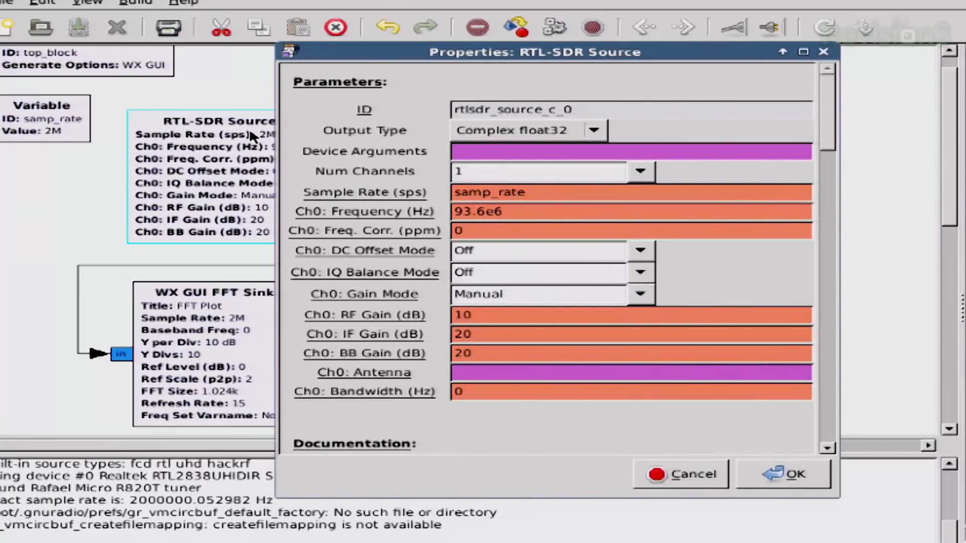
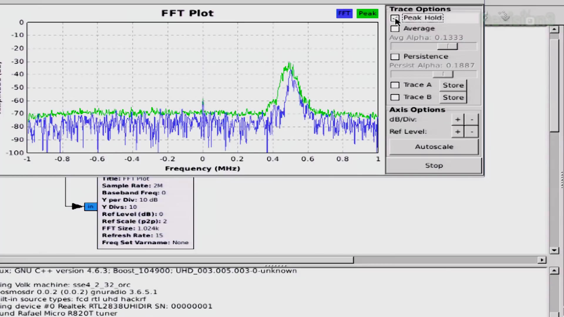
Regardless, when they run this basic graph, they get a spectrum showing a single signal 500 kHz above their center frequency. This gives a center frequency of that signal of 93.6 + 0.5 = 94.1 MHz. At the very least, they have a signal within the input of their SDR.
The Resampling Issue
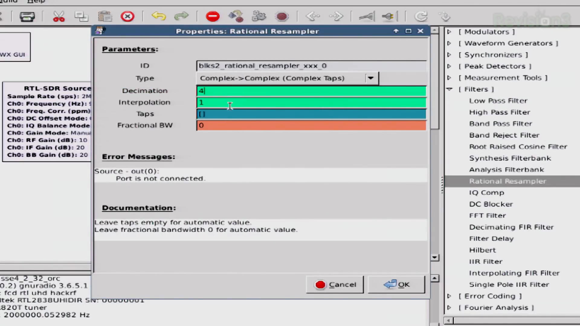
The very first thing they add is a "Rational Resampler" block. A critical concept in digital processing is resampling. This means to change the sample rate of a signal, either through interpolation (increasing the sample rate) or decimation (decreasing the sample rate).
Darren, at one point, says, "We need to resample this so that our computer can more easily decode all of it." True enough. They set the sample rate of their Realtek RTL-SDR to 2 MHz. An advantage of a higher sample rate is that your computer can access more spectrum. A disadvantage is that it has to process more spectrum. Darren and Shannon add a "Rational Resampler" block, and set the decimation value to "4". This now means that the sample rate at the output of the "Rational Resampler" block is 500 kHz (2 MHz / 4 = 500 kHz).
This is the second, major problem with their receiver. They are centered at 93.6 MHz. Their only signal is at 94.1 MHz, which is 500 kHz away from their center. They just set their sample rate to 500 kHz. This means that they should only be receiving spectrum that is +/-250 kHz of their center frequency. The maximum frequency should be able to receive should be 93.6 MHz + 0.25 MHz = 93.85 MHz. Again, their signal is at 94.1 MHz. It deviates a maximum of 75 kHz below this, and with its modulation, you can see decent energy down to -100 kHz (94.0 MHz). We have a 150 kHz gap between the top end of our receiver (93.85 MHz) and the bottom end of our signal (94.0 MHz).
Here's my first bit of ignorance. I'm quite familiar with the "QT GUI" versions of the various blocks. That's pretty much all I've used since I started playing around with Gnu Radio. In the "QT GUI" version, any time there's a decimation, the block performs a lowpass filtering first. Does this happen in the "WX GUI" version? I don't know.
Here's my hypothesis. If there is no filtering before the actual decimation, then the entire 2 MHz spectrum seen on their spectral display will be "folded down" into the final 500 kHz spectrum. We can even do a quick bit of math to find out where the signal would be centered if it was indeed "folded down" due to the decimation. Since it is 500 kHz from the center, and the new sample rate is 500 kHz, it would wind up being centered in the new, decimated spectrum. Again, this is assuming there's no filtering before the actual act of decimation. But if my hypothesis is correct, then this would explain how their receiver still worked. The signal would have been "folded down" into the center of their spectrum. Even if the signal was filtered before decimation, it's possible the signal is still strong enough to demodulate it. (Remember: Filtering typically does not eliminate a signal, it just makes it weaker.)
The Filter
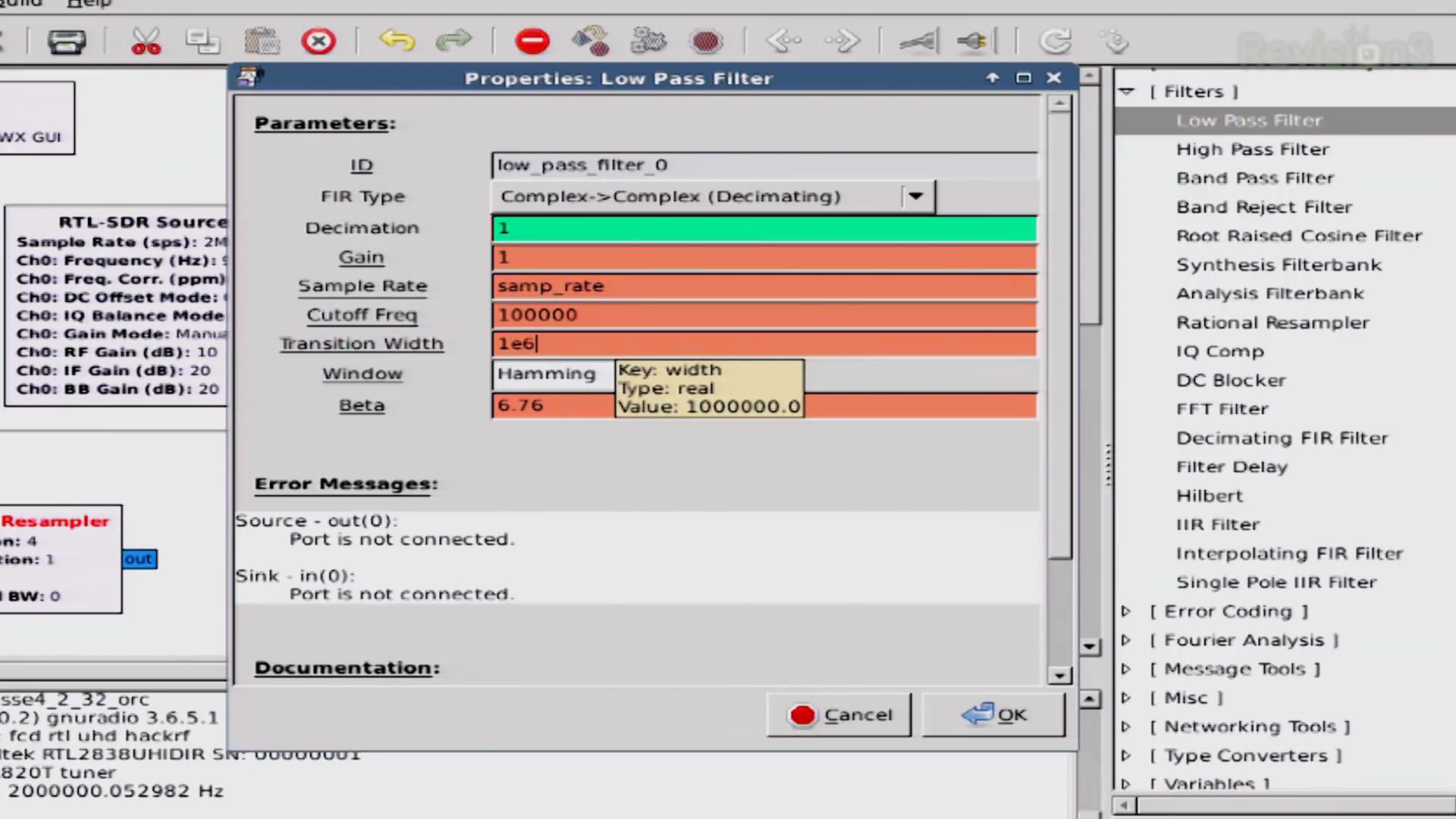
The next thing they add is a "Low Pass Filter" (which I and just about every engineer I know spell with just one word, "lowpass"). Their use of a lowpass filter is correct. They're processing complex samples. Complex samples means our signal is above and below 0 Hz (both positive and negative frequencies, respectively). A lowpass filter when operating on complex samples effectively gives you a "bandpass" filter since the signal should be centered at 0 Hz.
They set the cutoff frequency of the lowpass filter to 100 kHz. This is also correct. A FM broadcast station in the US is provided 200 kHz of bandwidth. They typically use 150 - 180 kHz for the signal, and the rest as a "guard band" to prevent interference with surrounding stations. As I said before, a lowpass filter on complex samples will be the same as a "bandpass" filter. It will operate such that it filters +/-100 kHz, giving you 200 kHz of bandwidth. So far, so good.
It's their last value for the filter that puzzles me. They set the "transition" width of the filter to 1 MHz ("1e6"). The "transition width" in a filter is the part of the filter that begins to go from no to little attenutation (the passband) to full attenuation (the stopband). Most people try to design filters with sharp transition widths. I normally set mine for 10 kHz or so. Why did they set it to 1 MHz? This is where I shrug and say, "Don't know."
The Demodulator and Resampler
Their next, two blocks are, respectively, the frequency demodulator followed by another resampler. The specific demodulator they use is the "WBFM Receive". It combines a demodulator with a resampler. If you set the initial sample rate correctly, you can create a graph for a FM receiver with just four blocks. The "WBFM Receive" block will do both demodulation and decimation; it will not perform interpolation (increase the sample rate), though. With the sample rate at the input of the demodulator (the "WBFM Receive" block) of 500 kHz, they would not have been able to decimate this sample rate to get to one of the values acceptable to the audio card. Audio card rates are typically 8 kHz and some of its interpolated values (16, 24, 32, 48 kHz) or 44.1 kHz and its decimated values (22.05, 11.025 kHz). You can't get to any of these values from 500 kHz by just decimation. There has to be some interpolation. This, in turn, means they had to use a resampler. The second resampler sets the output sample rate to 48 kHz. This gets ported into an "Audio Sink" (which is the sound card on the computer).
At this point, they both started running their graphs. I heard some audio, but also a fair amount of noise. Okay, while reviewing the video for this post, at the part where they begin the graph, Darren says, "Oops. I actually need to tune mine properly, here on 96.3." This means he realized he was not on a signal and tuned it to an actual station frequency (which I'm assuming is the 96.3 MHz). But Shannon (so far as I know) kept hers tuned to the 93.6 MHz center frequency. Again, the only station shown in her spectral display was at 94.1 MHz. How was she able to receive this signal with such a bad graph? She didn't retune to something else. A few moments later, the video shows her stopping the graph. For a brief moment, we see her waterfall display. She's still tuned to 93.6 MHz; the only signal is still at 94.1 MHz. Yet she has audio. Again, how?
The video is 6 years old. It's OBE. But I'm still curious as to why it actually worked. Everything that I've just explained above says it should not have worked. Yet it did.
When you compare their graph with the very basic one I created, there are two differences. The first is the "Rational Resampler" block between the RTL-SDR source, and the lowpass filter. The second is the "Rational Resampler" block between the demodulator and the audio sink.
The second "Rational Resampler" was just to get the sample rate to one the audio card could handle. If I had not chosen the sample rate for my receiver as 2.4 MHz but 2 MHz, as well, I, too, would have needed a resampler block between the demodulator and the audio card. That resampler is irrelevant to the discussion.
The biggest difference is the first "Rational Resampler" block between the RTL-SDR source block and the lowpass filter block. It's that very block, combined with the fact that they were not tuned to a FM station, that means their graph should not have worked.
Again, for some reason, it did. Hmmmmm.