
Random Quote Board
Analog Video Transmissions with hacktv and Gnu Radio
I created and demodulated digital television signals, specifically the ATSC version 1, in a previous post. This month, I'm going to take a step back and look at analog television video, thanks to the work of Philip Heron and his "hacktv" code.
hacktv allows for sending the samples directly to a HackRF. For this post, I'm going to store the created samples as files. This will allow for transmitting with other systems besides the HackRF.
Analog Video Review
There are three versions of analog video used for broadcast (with a few special cases), and a plethora of other analog video formats such as slow scan TV. We're going to cover broadcast video in this post. Specifically, we'll look at NTSC, PAL and SECAM.
Assumptions
If you wish to follow along with this post, I'm going to assume that you have hacktv already installed.
You will also need a MP4 video which you will convert into an analog video signal. Most smartphones nowadays store their video in MP4 format. If you do not have one, then you can use ffmpeg to convert an image (JPEG, PNG, etc) into a MP4 video. NOTE: If I understand it correctly, installing hacktv also installs ffmpeg. The ffmpeg command to convert a still image into MP4 video is:
ffmpeg -loop 1 -i still-image.jpg -t 30 -r 30 video.mp4
where:
- -loop 1: loop the same image over and over til the end.
- -i still-image.jpg: This is the still image that you're converting to video.
- -t 30: The length of the video, in seconds. This says convert the still image into a 30 second video clip.
- -r 30: Frame rate, in frames per second, for the final video.
- video.mp4: This will be the output video file.
Baseband Video
I'm going to start with a baseband NTSC signal. For this, I'm using the same video of the Cornell Chimes as for the post I did on ATSC. I started by opening a terminal and navigating to the same folder containing the MP4 video file. I then entered the following command:
hacktv -o cornell-chimes-ntsc.rs16 -m ntsc -s 9000000 cornell-chimes.mp4
where:
- -o cornell-chimes-ntsc.rs16: This is the output file. I'm using the extension ".rs16" since the file consists of real, signed, 16-bit samples (a "short" in general programming and Gnu Radio terms). As the hacktv Github documenation states, "The default output is int16. The TV mode will determine if the output is real or complex." Since this is baseband (unmodulated), then the output will be real.
- -m ntsc: create a baseband NTSC signal. NOTE: Using this option also means that you will NOT have any audio on the signal.
- -s 9000000: This is the sample rate of the output file. NOTE: As of this writing (September 2025), you have to spell out the value. You cannot use abbreviations such as "9e6".
- cornell-chimes.mp4: This is the input MP4 file.
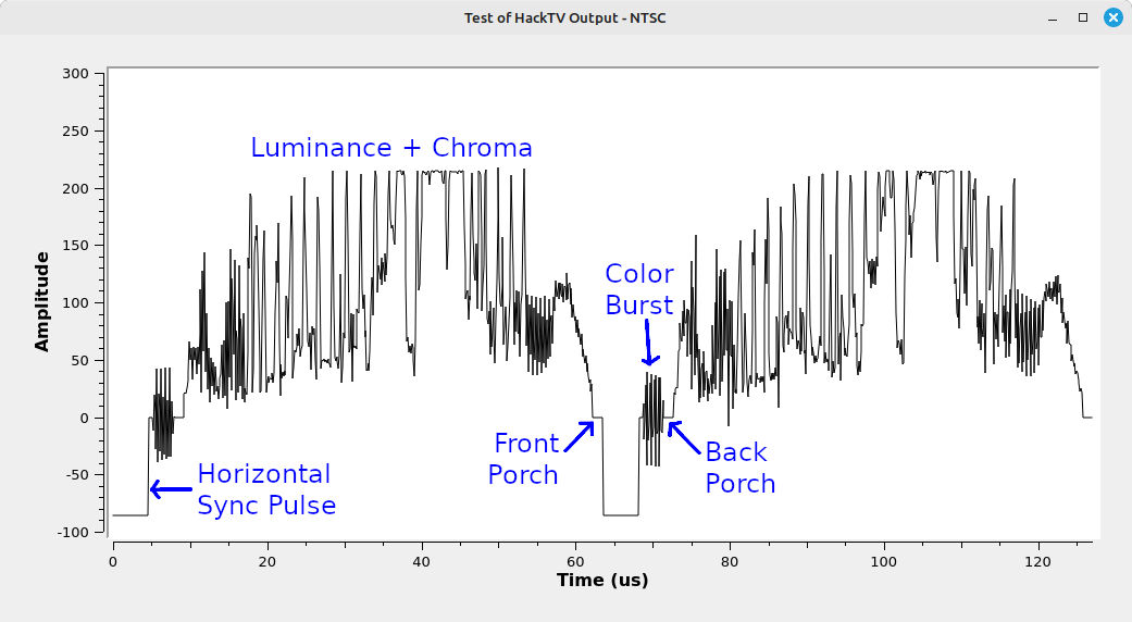
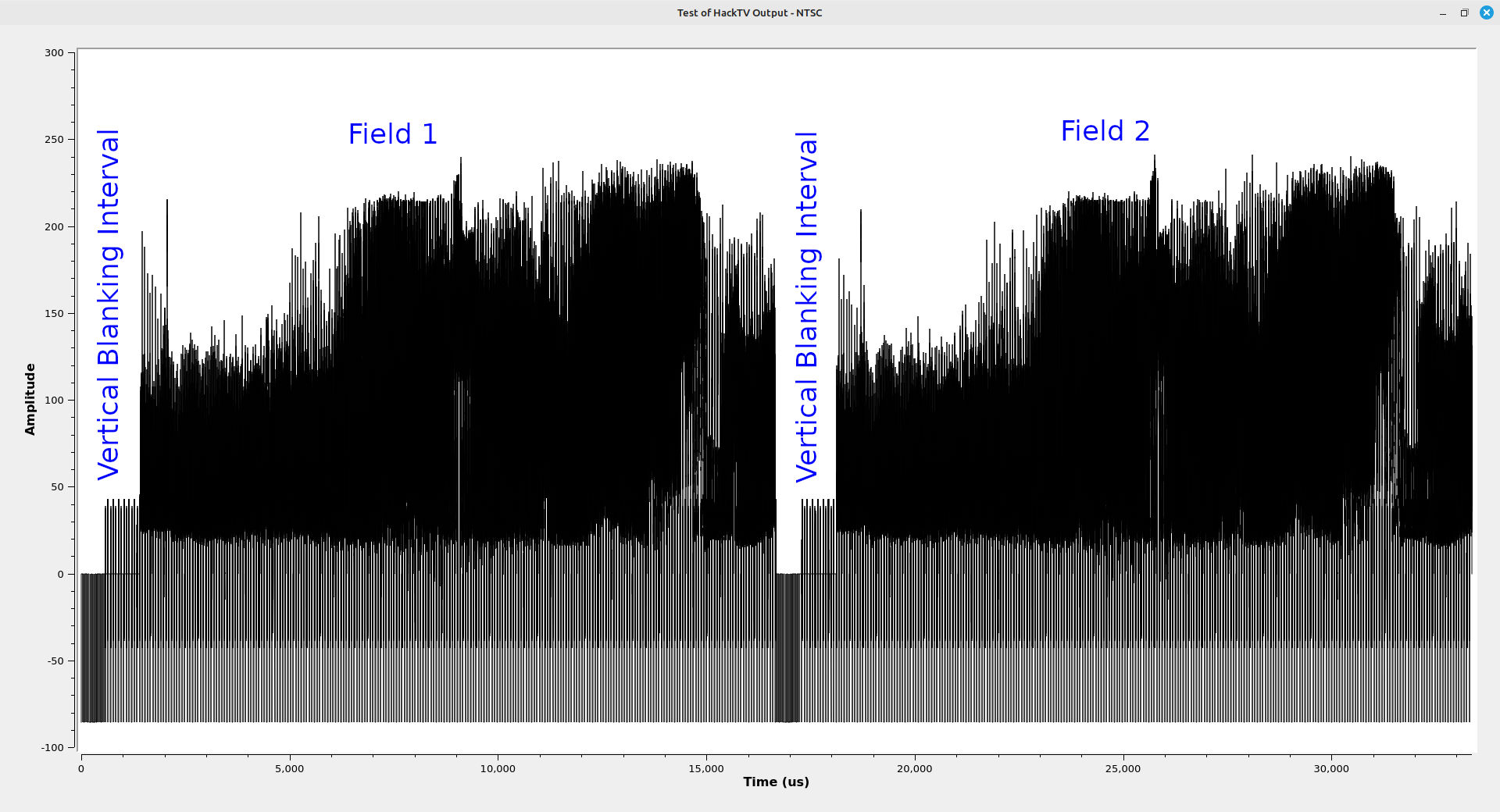
This converts the digital .MP4 into an analog NTSC baseband signal, though only the video (no audio). This baseband video signal has the following appearance in the time domain:
Modulated NTSC
It's also possible to have hacktv create a fully-modulated NTSC signal. To do this with the same MP4 file as above, I used this code:
hacktv -o NTSC-modulated-chimes.cs16 -m m -s 13500000 cornell-chimes.mp4
where:
- -o NTSC-modulated-chimes.cs16: This is the output file, which has a sample type of complex, signed 16-bit (short)
- -m m: Create a modulated NTSC signal with both video and audio.
- -s 13500000: Use a sample rate of 13.5 MSps. NOTE: As of this writing, these sample rates have to be in integer format.
- cornell-chimes.mp4: The input MP4 file.
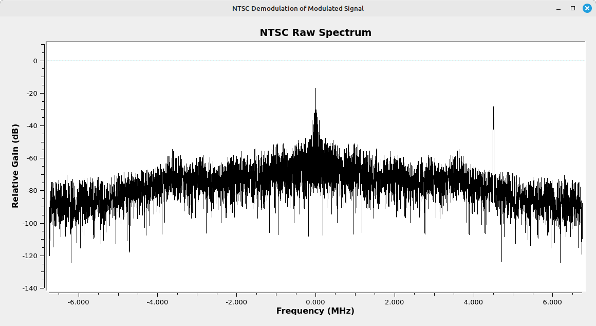
The modulated signal that hacktv creates does not conform with the standards for bandwidth. Here's the raw spectrum after converting the MP4 to modulated NTSC:
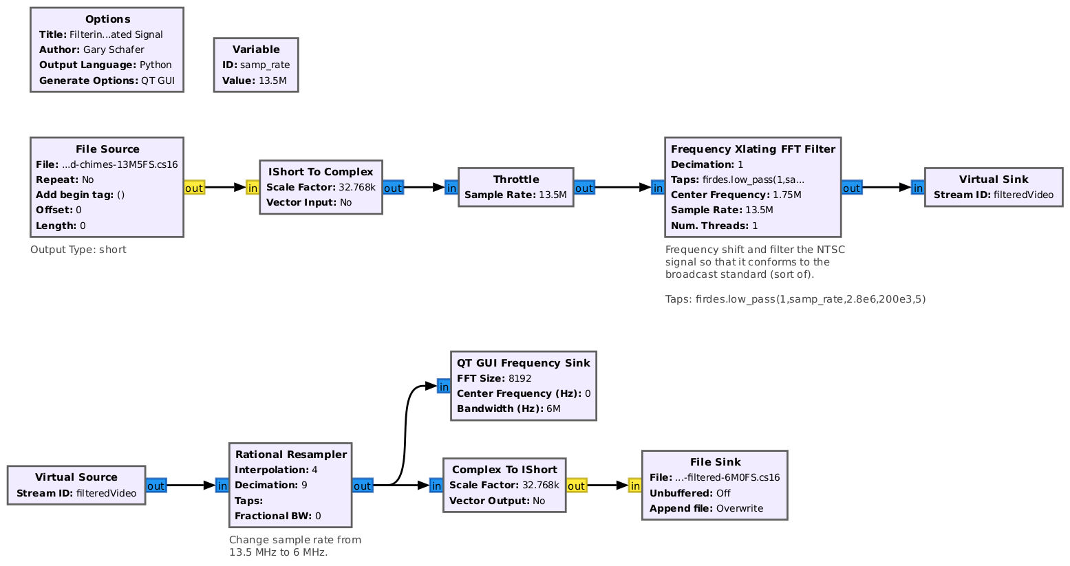
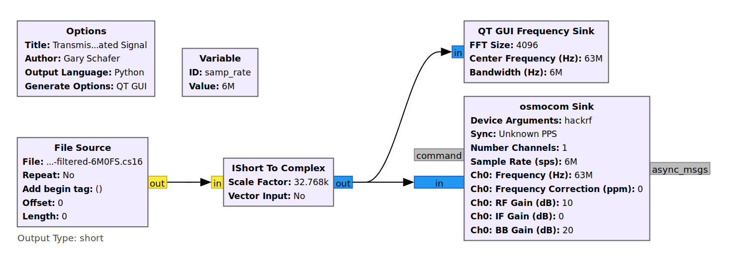
To adjust the spectrum so that it is similar to a broadcast station, we need to shift the spectrum and filter. We can also adjust the sample rate. Here's a flowgraph to do just that.
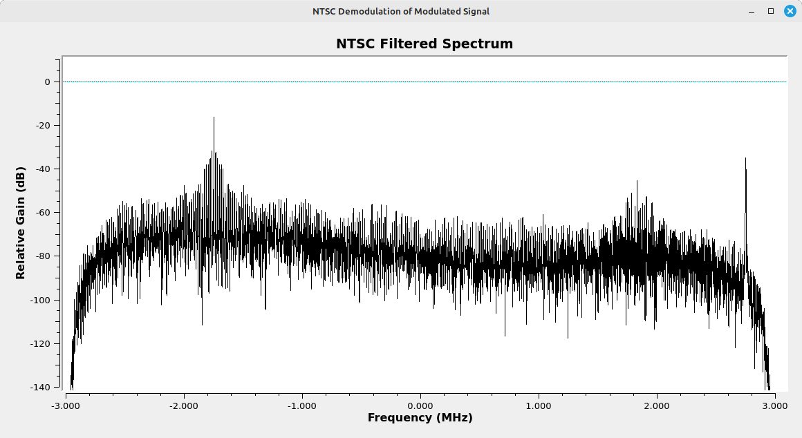
I created a basic flowgraph outputting this filtered file into a HackRF One, and sending the output of the HackRF into a television with an analog tuner.
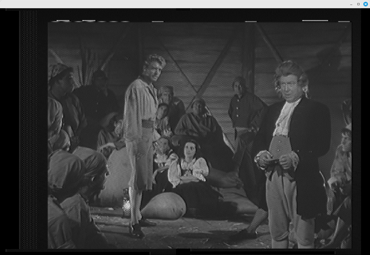
The video was quite good, as seen below.
Modulated PAL
I used hactkv to also make a PAL signal. The specific command I used was:
hacktv -o PAL-modulated-chimes-16M0FS.cs16 -m i -s 16000000 cornell-chimes.mp4
where:
- -o PAL-modulated-chimes-16M0FS.cs16: Output file.
- -m i: Output file is a modulated PAL signal with NICAM stereo audio.
- -s 16000000: sample rate of 16 MSps
- cornell-chimes.mp4: input MP4 file
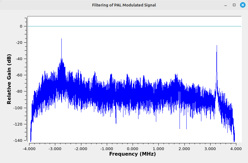
The raw spectrum from this PAL signal is as follows:
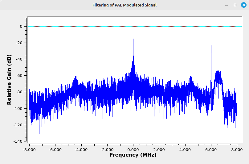
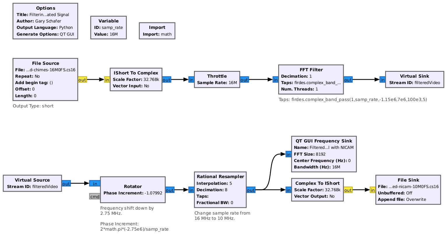
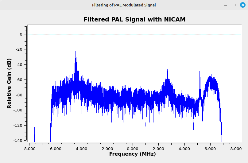
Filtering this signal is slightly different from standard signals because of the NICAM audio subcarrier. It actually extends slightly into the next channel higher in the spectrum. To keep from cutting off part of this signal, I only lowered the sample rate to 10 MHz after filtering from the original 16 MHz.
You can create a PAL signal without the NICAM subcarrier using the "--nonicam" option, as follows:
hacktv -o PAL-modulated-chimes-nonicam-16M0FS.cs16 -m i -s 16000000 --nonicam cornell-chimes.mp4
where:
- -o PAL-modulated-chimes-nonicam-16M0FS.cs16: output file
- -m i: output type is PAL
- -s 16000000: sample rate of 16 MHz
- --nonicam: option to not use the NICAM subcarrier
- cornell-chimes.mp4: input MP4 file
Modulated SECAM
Making a modulated SECAM signal is similar to the others. I used the following command to make a basic SECAM signal:
hacktv -o SECAM-modulated-chimes-16M0FS.cs16 -m l -s 16000000 cornell-chimes.mp4
where:
- -o SECAM-modulated-chimes-16M0FS.cs16: output file
- -m l: output type is SECAM
- -s 16000000: sample rate of 16 MHz
- cornell-chimes.mp4: input MP4 file
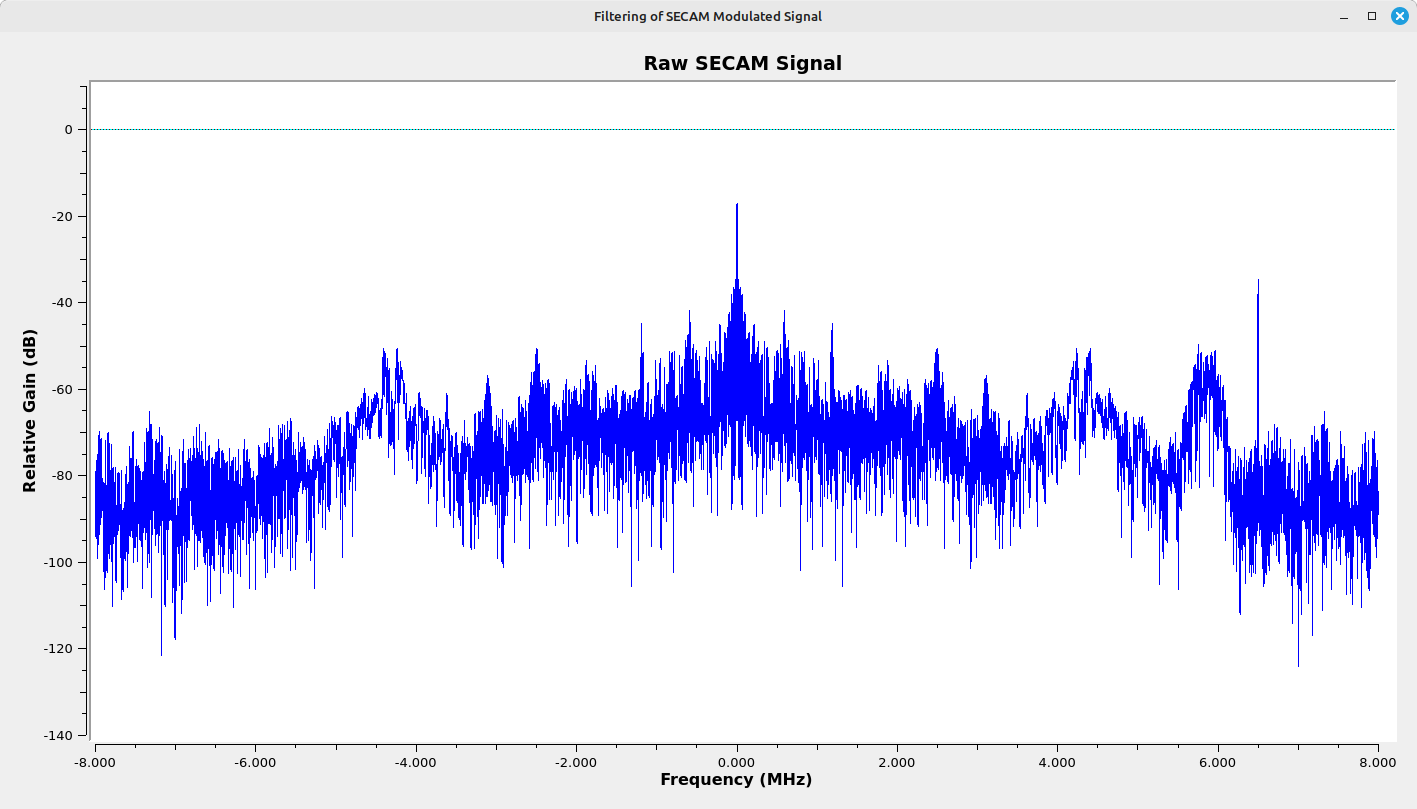
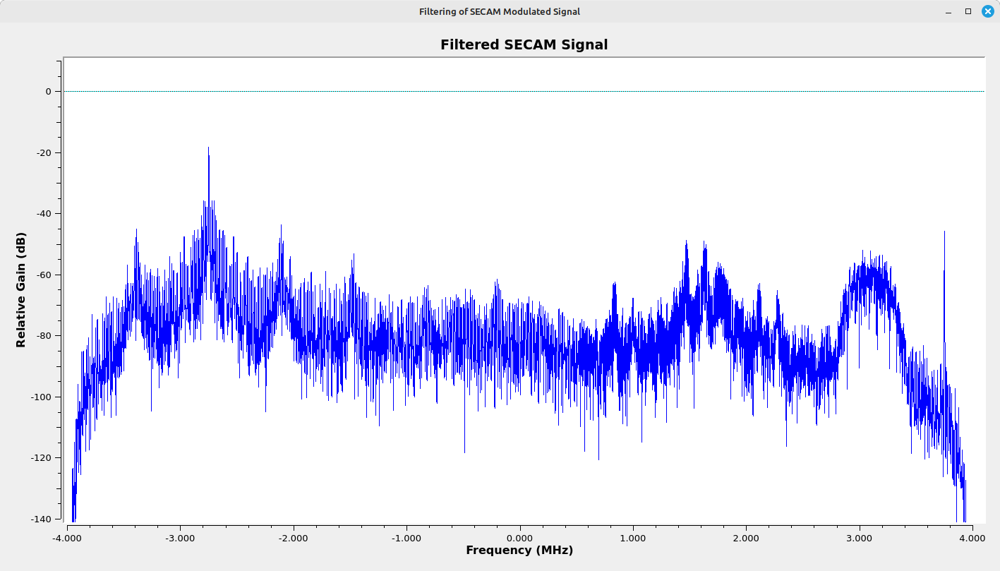
This creates a raw spectrum that is somewhat similar to the PAL spectrum, except the NICAM subcarrier is lower in frequency than the analog audio subcarrier.
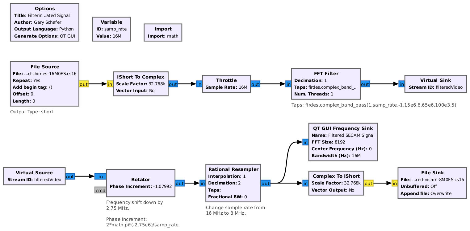
I used the following flowgraph to filter, shift and resample the signal. (NOTE: I could have simplified this flowgraph, but modifying the flowgraph would have been more work than just changing some values in the flowgraph I used for the PAL. So I went with "lazy".)
Demodulating with GRC
As I'm an American (not to be confused with a "Murican"), I don't have ready access to either PAL or SECAM demodulators. Both the TVs I have in my house only work on NTSC. This means that, in order to test the PAL or SECAM signals, I'll have to make a "tuner" using Gnu Radio.
Fortunately, I've already done that. All we need to do is to modify the flowgraph for amplitude demodulation and add an audio demodulator.
Setting the Sample Rate
TL;DR: The video clock rate should be 13.5 MHz for NTSC, and 16 MHz for PAL or SECAM.
Video is displayed one horizontal line at a time. Each line has a certain time length. The inverse is that a certain number of lines are drawn each second. This is the horizontal line rate. This horizontal line rate is based on the specific video standard, with PAL and SECAM having identical line rates. In order to display an analog video signal on a digital display, each horizontal line has to be drawn with an integer number of samples. This is where it gets tricky. The number of samples displayed on the screen is the sample rate divided by the horizontal line rate. If this number is not an integer, then the signal will not line up properly.
The question becomes, "What clock rate should we use?"
A quick discussion about how NTSC signals are clocked. According to The Television Engineering Handbook (my emphasis added):
In color systems, the horizontal and vertical rates are rigidly locked to (actually divided down from) the color subcarrier frequency. ("Television Engineering Handbook: Revised Edition", K. Blair Benson (editor and coauthor), McGraw-Hill, Inc, New York, 1992)
The color subcarrier frequency is approximately 3.58 MHz, and can be calculated as follows:
\( \Large f_{chroma} = \text{5 MHz} \times \frac{63}{88} = \text{3.5795455 MHz} \)
Both the horizontal and vertical frequencies can be calculated from this as follows:
\( \Large f_{horz} = f_{chroma} \times \frac{2}{455} = \text{15734.2657 Hz} \)
\( \Large f_{vert} = f_{horz} \times \frac{2}{525} = \text{59.94 Hz} \)
Another way to calculate these various clock rates is to start with the horizontal sync rate, which can also be calculated as follows:
\( \Large f_{horz} = \text{2.25 MHz} \div 143 = \text{15734.2657 Hz} \)
The fact that this clock rate is a frequency (such as could be created by a crystal oscillator) decimated by a single integer simplifies our problem. That's because, if we use an integer value of this sample rate (for example, 2.25 MHz, 4.5 MHz, 6.75 MHz, 9 MHz, etc), then the number of pixels we need to display the image will also be an integer value. That works very well in Gnu Radio with the Video SDL Sink block. For example, if we use a 4.5 MHz sample rate, then we would need 286 pixels to display one line of video. However, since the sample rate also sets the maximum bandwidth allowable combined with the fact that NTSC is a 6 MHz channel, then we need a sample rate of at least 6 MHz. Given we need an integer multiple of 2.25 MHz, this means the lowest sample rate we should use for a modulated NTSC signal should be 6.75 MHz. You may have noticed that the sample rate used for the hacktv command above was a very specific value, 13.5 MHz. That's 6 x 2.25 MHz. To display this video signal, we could use a Video SDL Sink with a horizontal width of 6 x 143 = 858 pixels. In the same vein, PAL and SECAM should be 16 MHz, which requires 1024 samples for each horizontal line.
hacktv Sample Rates
hacktv requires that the video sample rate be an integer multiple of the horizontal sync rate. Even if you try to set the sample rate to a value that is not an integer multiple of the horizontal rate, hacktv will set the sample rate to the closest value to one of the integer values. For example, what happens if you try to set the sample rate to 11 MHz? This value would require a multiple of the horizontal sync rate of (11 MHz/15834.2657 Hz) = 699.11. The closest integer is 699. Hence, hacktv will set the sample rate to (15734.2657 Hz)(699) = 10.998251 MHz.
Summary
Between this and the previous post, you should be set for making a video receiver for pretty much any broadcast analog video standard (NTSC, PAL or SECAM). I'm not certain what my next post will be, but perhaps I'll cover slow scan TV signals. Or something else. Guess we'll find out!
Rastering Analog Video with Gnu Radio
I attended Shmoocon a few years ago, and was able to take part in my first "capture the flag". One of the "flags" required viewing an analog video signal. This was before I'd begun playing around with SDRangel, so I needed some way to raster the video signal without requiring a TV set (which wasn't handy at the time). I came up with a Gnu Radio flowgraph to do it. I was in a hurry at the time, so my first flowgraph was barebones. I've since enhanced it. That's what I'll cover here.
Let's get a couple of things out of the way right now about what this flowgraph will (and will not) do.
- This flowgraph will work on NTSC, PAL or SECAM signals.
- I'm just going for video. I didn't add audio demodulation (if any) on the signal.
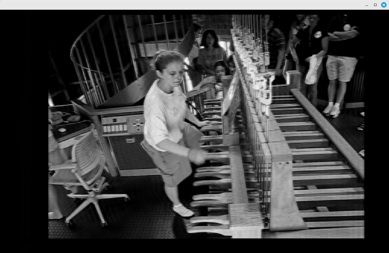
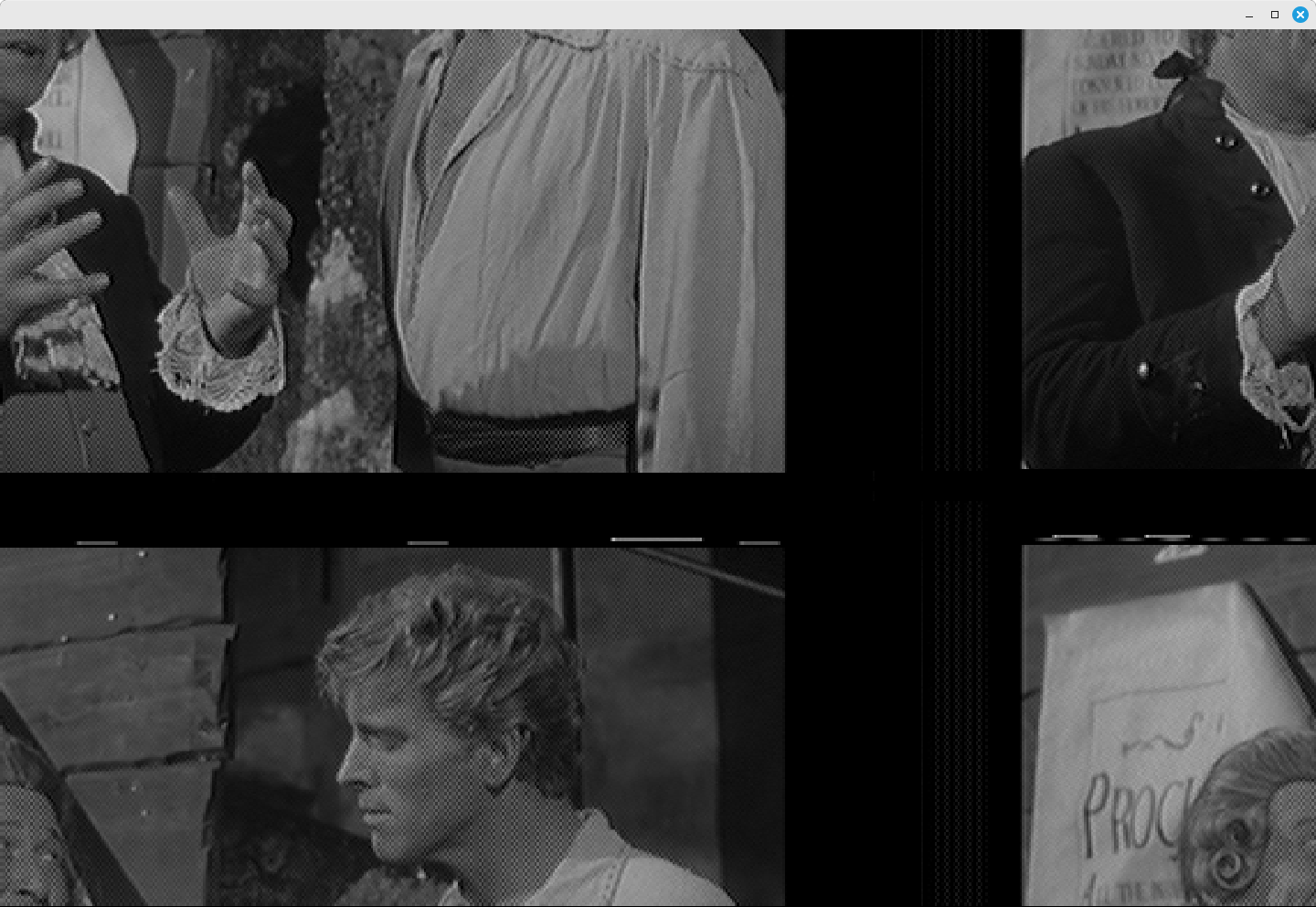
- This flowgraph will only show the image in black and white. Getting to the color means properly and precisely demodulating the chroma subcarrier signal, plus figuring out how to separate out the Y, U and V signals. That's a bit more than I want to do and, frankly, I'm not certain how I would do it in Gnu Radio.
- For the purposes of this flowgraph, I consider PAL and SECAM to be the same thing. Since I'm not dealing with color (see previous comment), the timing is my only concern. The timing for these two types are equivalent.
- Gnu Radio does not currently have a way to sync with the video signal. Instead, we'll create our own sync that should be good enough.
- I didn't setup up the screen controls and display for neatness. I didn't bother adding values to the "GUI Hint" properties to any of the control or display blocks.
I'm going to jump into the flow of rastering, with the assumption that you, the reader, already has a basic understanding of analog video rastering. If not, well, go ahead and try it anyway if you have a known analog video transmitter near you! What have you got to lose?
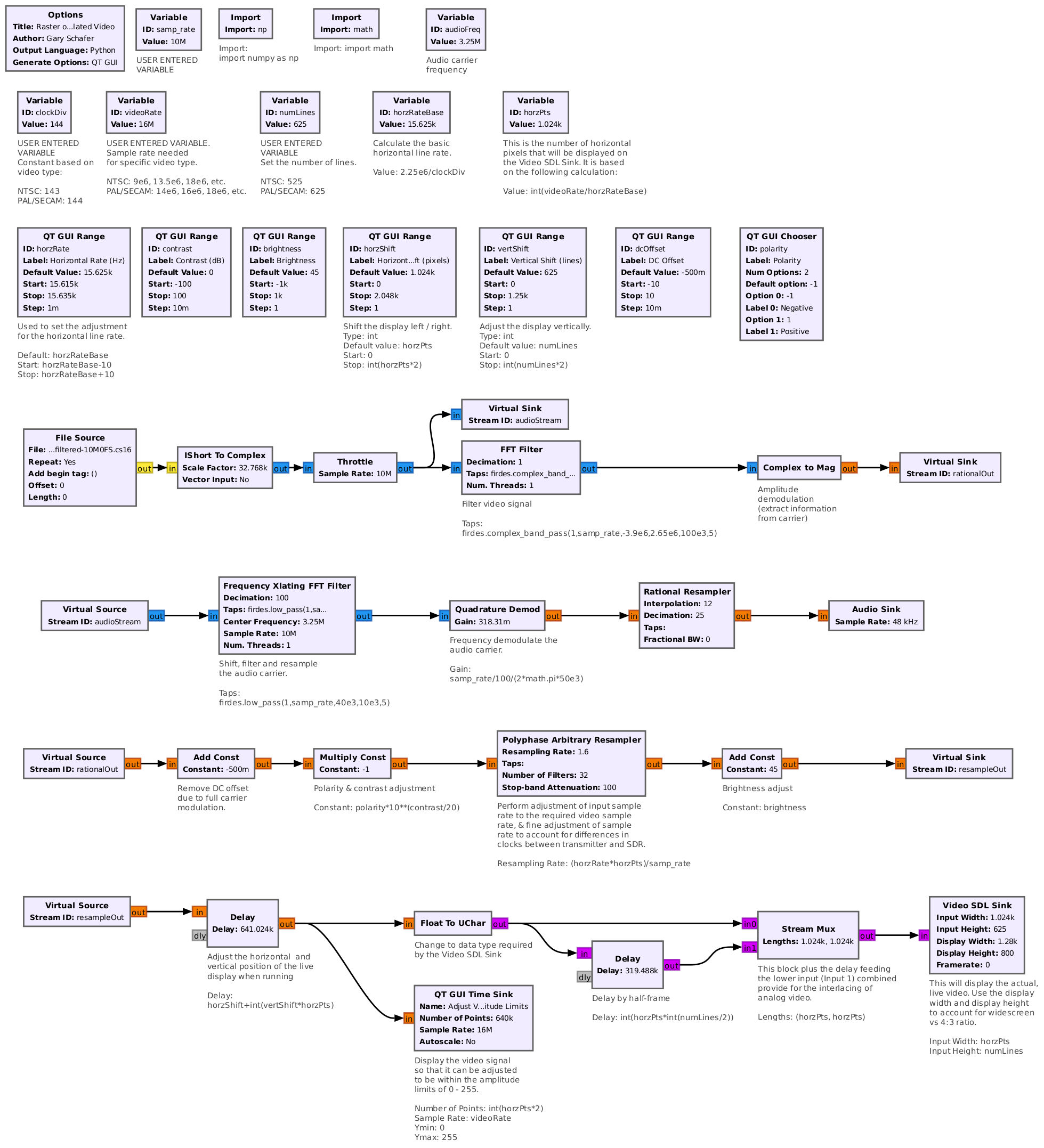
General Flow of Rastering with Gnu Radio
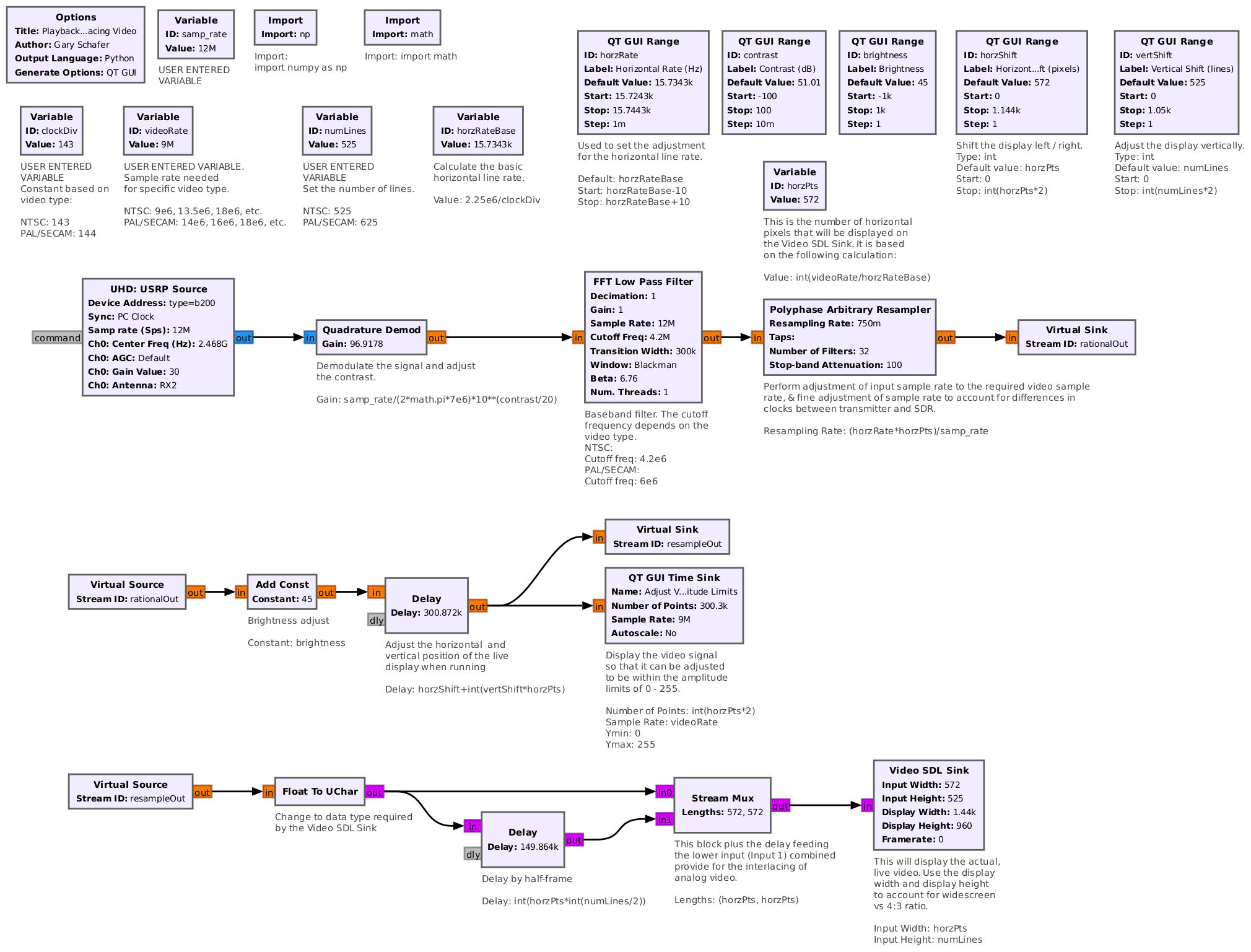
I've also made the flowgraph available if you wish to download it.
Here's how to work with this flowgraph. Before running it, enter the appropriate values in the blocks marked with the comment, "USER ENTERED VARIABLE". These are:
- the sample rate of the flowgraph input
- the desired video sample rate
- the clock divisor for the video type
- the number of lines in the video type.
When you run it, the flowgraph:
- Performs calculations based on the video type (NTSC, PAL/SECAM). These include calculating the horizontal line rate, the number of pixels in the width of the Video SDL Sink, the limits for the horizontal line rate adjustment, and the maximum limits for the horizontal and vertical shift.
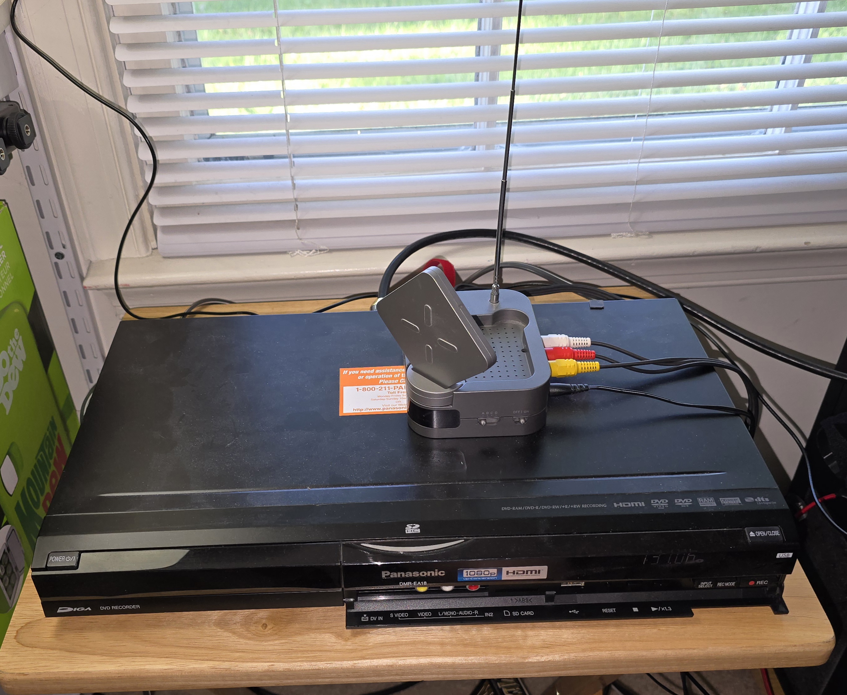
- Inputs the signal. This can be from a SDR, from a file, or from a network connection. For this post, I used the USRP B200-mini.
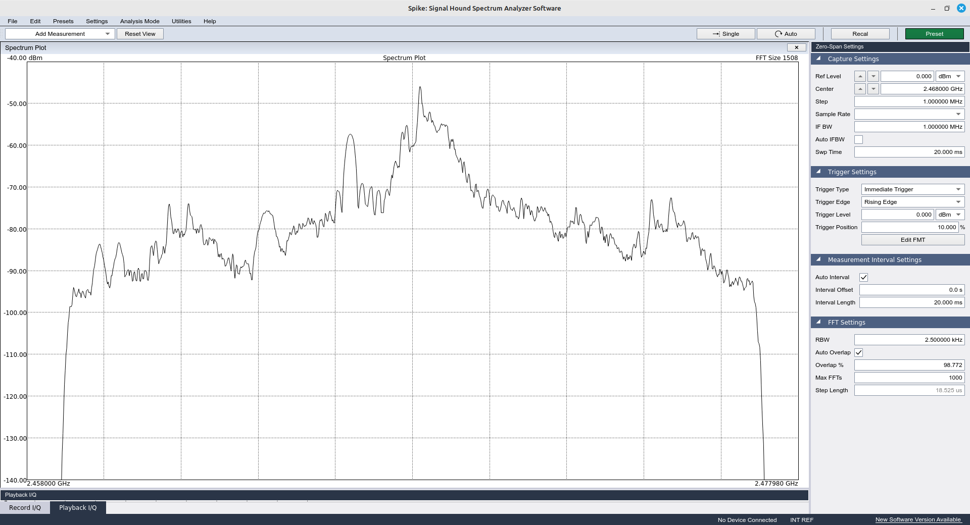
- Filters the signal. This will either be based on the signal and SDR (either with the sample rate or with a manual setting for the SDR's input bandwidth), or with an external filter. I'd use an external filter if I was going after an AM signal that used VSB. If there was an audio signal on the next channel down (meaning within a few MHz of the video carrier), I'd throw in a filter to get rid of that before demodulation. But for FM video? Those are wide enough bandwidth that by setting the sample rate properly, the signal will already be filtered just based on the sample rate.
- Demodulates the signal. For those outside of the USA, you may still have broadcast analog video signals. If that is what you're going for, then you'll need an AM demodulator (a "Complex to Mag" block works nicely). If you're going after an analog video transmitter such as a wireless video extender or perhaps a drone, those transmissions are FM (a "Quadrature Demod" block works here). For this post, I'm using an analog wireless video extender. It uses FM. Hence, the "Quadrature Demod" block.
- Filters the baseband signal. NTSC, for example, uses the bottom 4.2 MHz for video. This includes a chroma subcarrier at roughly 3.58 MHz. For FM video, audio subcarriers exist at 6 and 6.5 MHz, while for AM broadcast video, the audio subcarrier exists at 4.5 MHz. This filter gets rid of any audio subcarriers.
- Adjusts the sample rate. There are two parts to this. The first is to get to the approximate sample rate required by the specific video standard (namely either NTSC or PAL/SECAM). The second step is to get the precise timing so that the image will not drift on the display. I do both steps with the "Polyphase Arbitrary Resampler".
- Adjusts the amplitude of the video signal. The Video SDL Sink (the block we'll use to display the video signal) will use an unsigned 8-bit integer (uchar). This means we need to have amplitudes between 0 (black) and 255 (white). I'm performing this in two blocks. The first is a multiplication that takes place in the "Gain" setting of the "Quadrature Demod" block. This multiplication is essentially a contrast adjustment. The other block is an "Add Const" (add a constant) to adjust the level of the overall signal and keep it within the 0 - 255 limits. This is essentially a "brightness" adjustment.
- Shifts the video display so that it is centered horizontally and vertically. Once you have the timing set juuuuust right, the display should not be moving, but it doesn't mean it will be centered, either horizontally or vertically. Therefore, I'm using a "Delay" block to adjust these positions. NOTE: This block is not absolutely required. You can get away without it by using the timing adjustment earlier. But this is tricky. However, if you're operating at the very edge of your system (seeing overflows from the SDR, primarily), then you can delete this block and just use the timing.
- Interlaces the lines. As I said, broadcast analog video is interlaced. I'm using two blocks to interlace the video, a "Delay" block in combination with a "Stream Mux" block. The delay adds a half-frame (one field) delay, then multiplexes the non-delayed and delayed to provide for the interlacing.
- Finally, displays the video. The Video SDL Sink display ratio (say, widescreen or 4:3) can be set using the "Display Width" and "Display Height" values. I'm using a relatively large size because I'm fortunate to have multiple monitors. If you're operating on a small laptop or tablet screen, you may wish to decrease these values to a size that works for your screen. This will probably take some trial-and-error.
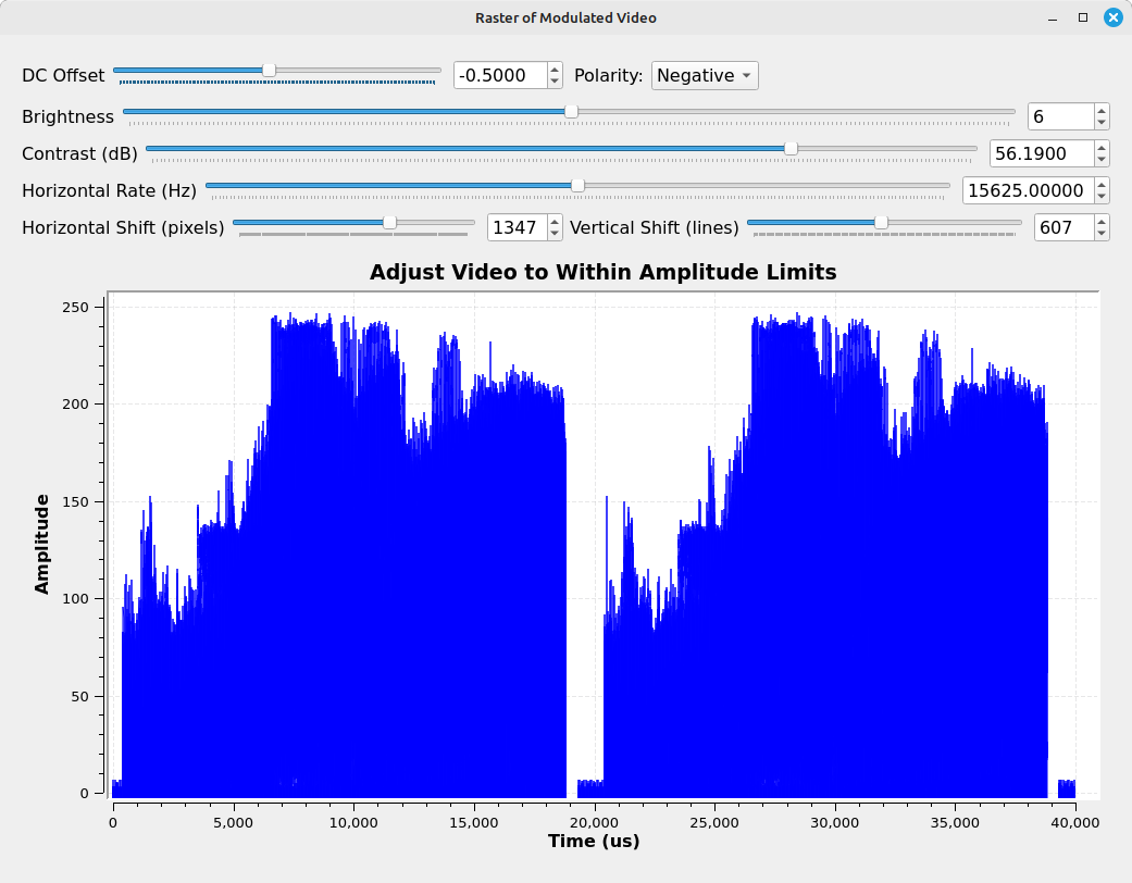
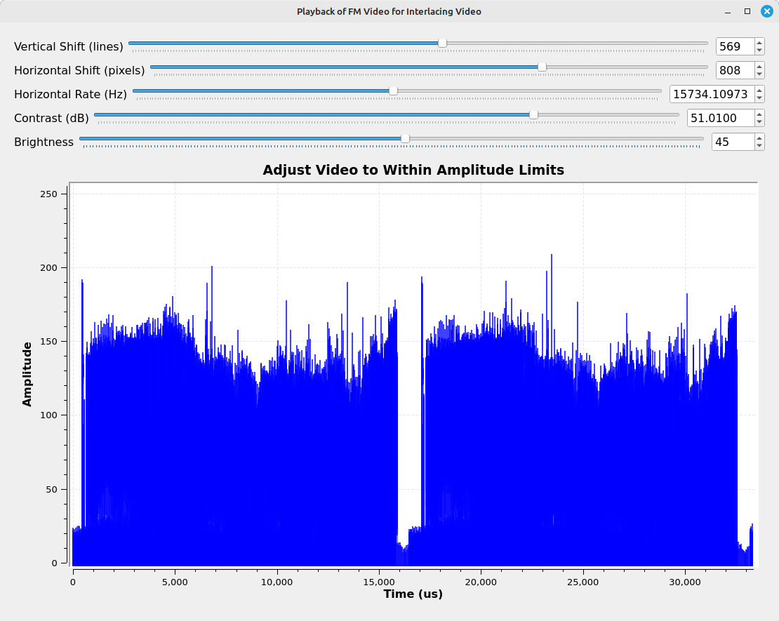
Once the flowgraph is truly running, you'll need to make a few adjustments. I'll give the general flow here.
- If needed, adjust the center frequency of your SDR to that of the video transmitter, then adjust the appropriate gain values of that SDR so that you have a decent signal strength.
- Once you have a video signal on the time display, adjust the contrast and brightness controls so that the signal amplitude extends as much between the top and bottom of the display as possible.
- Adjust the horizontal rate. This is what sets the sync for the signal. The rate is in Hz, but the step size is 1/1000th of a Hz. This means it will change slooooowly. You can try sliding the slider manually. I tend to use the up / down arrows. Anyway, once the signal stops drifting, you're set. I've set the limits for the timing to be within +/- 10 Hz of the video type horizontal rate. This has worked on pretty much every transmitter I've seen. HOWEVER, given the possibility that this will be used by many more people, if you adjust the sliders to the limit and it is still drifting, you'll need to increase those limits. ALSO, the video display will probably continue to drift very slowly over time. So this may need to be adjusted periodically.
- Adjust the position of the display using the horizontal and vertical shift sliders to center the display.
Final Notes
Here are a couple of other things I learned while I was putting together this flowgraph and this post:
- There's a difference in source blocks between the osmocom Source and the Soapy Source. For example, when I tested my HackRF One with the Soapy block, the resulting picture looked as if it was being overdriven. It appeared perfect when I used the osmocom Source block.
- Again, using the HackRF One, when I attempted to use sample rates of 16 MHz or greater, the image was illegible. It didn't matter which source block (osmocom or Soapy) I used.
- I was able to raster a FM video signal, which nominally has a bandwidth of 25 MHz, with a bandwidth of only 9 MHz. Normally, this would distort the signal beyond recognition, and yet it worked.
I normally only do one post a month, but I decided to throw this together now in order to have it for reference for my next post on hacktv. Til then!